TPS25750EVM Guide
Trademarks
All trademarks are the property of their respective owners.
1 Items Required for Operation
The following items are required to use the TPS25750EVM:
TPS25750D data sheet
TPS25750EVM
TPS25750 Application Customization Tool
20-V barrel jack adapter or DC power supply
USB Type-C cables
USB Type-A to USB Mirco-B cable
Notebook with a USB port
2 TPS25750EVM System Description
The TPS25750EVM is an evaluation board used to evaluate the TPS25750 which is a single-port USB Type-C PD controller with integrated power paths. The TPS25750EVM is powered by a 20-V DC barrel jack. If this type of barrel jack is not available, the board can also be powered from an external bench supply connected to the SYS_PWR test point (TP4), with the bench supply providing 20 V. The TPS51225 provides the 3.3 V needed for powering the TPS25750 as well as the TM4C123GH, or the Tiva, and the 5-V supply is connected to the internal 5-V source power path for the TPS25750.
The TPS25750D incorporates two internal power paths; one 5-V source only power path and one high voltage bi-directional power path. The TPS51225 connects to PP5V, and the BQ25731 connects to PPHV, the internal high voltage bi-directional power path. Configuring this power path to act as a source or sink is explained in further detail later in this user’s guide. The TM4C123GH is used to program the external flash connected to the TPS25750. The TM4C123GH converts the USB2.0 data sent over the micro-b connector to I2C, programming the external flash, which the TPS25750 will load during the next power cycle. Programming the TPS25750 is explained in further detail later in this user’s guide.
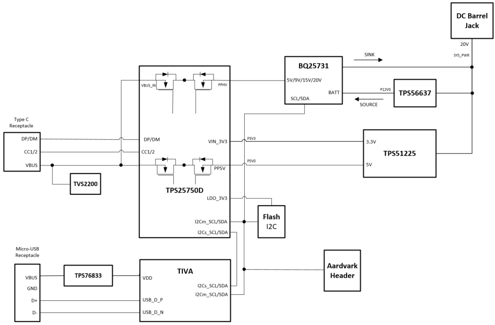 Figure 2-1 TPS25750EVM Block Diagram
2.1 Battery Charger (BQ25731)
The TPS25750EVM comes with an integrated battery charging solution using a BQ25731 buck/boost charger. The charger allows the EVM to operate as a source or sink from 5 to 20 volts at up to 3 amps. When acting as a sink, the TPS25750 negotiated the appropriate PD contract and enables the PPHV power path supplying power to the BQ. The BQ will then buck or boost the voltage to ensure the output is 12 volts (charging a 3S battery). When acting as a source, the BQ is powered by the barrel jack through the TPS56637 buck converter which simulates a 3S battery connection. The BQ will then buck or boost the 12 volts supplied from the TPS56637 to the desired output voltage which was negotiated in the PD contract.
2.2 Simulated Battery Connection (TPS56637)
Because the TPS25750EVM does not ship with a battery, a 12-V buck converter is used to simulate a 3S battery pack connected to the BQ25731RSN. This allows the customer to evaluate the performance of this EVM without having to supply their own 3S battery. The 12 V is generated by the TPS56637 buck converter which is powered from the 20-V DC barrel jack. When configured to use the on board buck converter, the EVM’s source capabilities are limited to 60 watts. An external battery/power supply can be connected to the EVM if more sourcing power is required (up to 100 watts) or if the customer needs to test the charging capabilities of the BQ device. To connect an external battery, remove the jumper J5 first and then connect the battery + terminal to the TP3 test point. It is important to note that in order to charge and external battery, the diodes D2 and D3 will need to be removed or shorted, so that current will not back flow the battery.
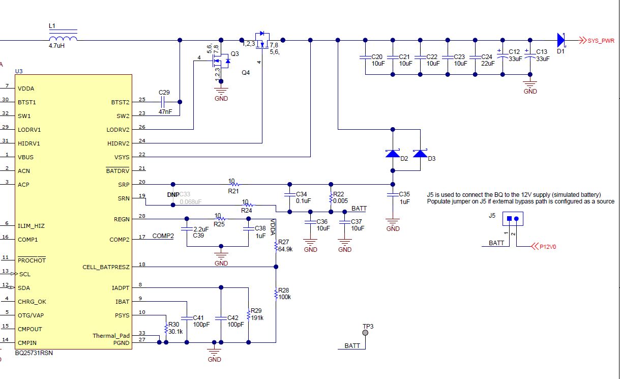 Figure 2-2 BQ Charger Partial
Schematic
Figure 2-2 BQ Charger Partial
Schematic2.3 Power Paths on the TPS25750EVM
The TPS25750EVM features two internal power paths. The internal power path connected to PPHV is bi-directional capable of being a high voltage source as well as a sink. The high voltage path can source up to 60 W and sink up to 100 W in the out of box configuration. There is also a power path which is a dedicated 5 V 3 A source path.
2.4 Aardvark™ Connector (J8)
This connector (J9) matches the Total Phase® Aardvark that allows the user to access the I2C pins on the TPS25750EVM.
3 Powering the TPS25750EVM
The main power supply for the EVM is the barrel jack (J9), which accepts 19 V to 20 V via a barrel jack adapter. Alternatively, the EVM can also be powered with an external power supply on SYS_PWR (TP4). The input voltage can range from 12 V to 20 V. The EVM can also run in dead battery mode and be powered from the USB Type-C™ connector. Connect a USB Type-C™ source to the USB Type-C™ port. This will cause for the TPS25750 to be powered solely by VBUS from the USB Type-C™ source connected, allowing for users to test the behavior of the TPS25750 in a dead battery scenario.
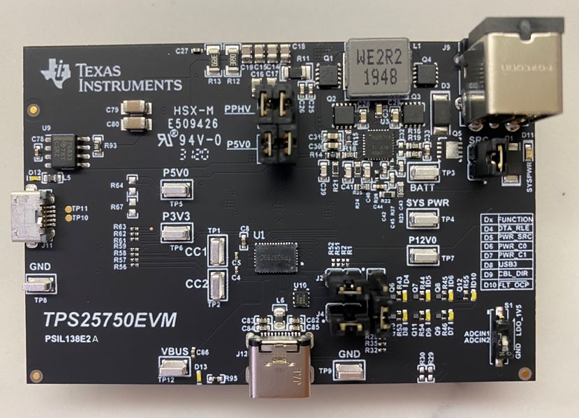 Figure 3-1 TPS25750EVM Power Connections
3.1 ADCin Setting (S1)
During the boot procedure, the TPS25750 will read the ADCINx pins and set the dead battery configuration and the I2C slave address for the PD controller based off of the pin inputs. The switch bank S1 can be switched to enable different dead battery conditions and I2C slave addresses. Keep in mind that S1A and S2A should never be turned on at the same time. The only safe switch configurations are listed below. A switch condition of 0 refers to the switch being open and a switch condition of 1 refers to a closed switch. These are also labeled on the EVM.
The two dead battery configurations offered are Safe Mode and Always Enable Sink. Their functions are listed below.
Always Enable Sink: The device always enables the sink path regardless of the amount of current the attached source is offering. USB PD is disabled until configuration is loaded.
Safe Mode: The device does not enable the sink path. USB PD is disabled until configuration is loaded. Note that the configuration could put the device into a source-only mode.
|
S1A | S1B | S1C |
Dead Battery Configuration | I2C Slave Address |
|---|---|---|---|---|
0 | 0 | 0 | Safe Mode | #2 |
0 | 1 | 1 | Always Enable Sink | #2 |
1 | 0 | 0 | Safe Mode | #1 |
1 | 0 | 1 | Always Enable Sink | #1 |
These two options are set with S1. The schematic for the ADCIN setting is shown below.
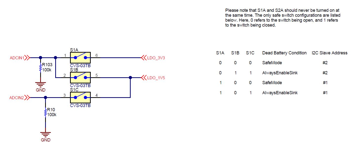 Figure 3-2 ADCIN S1 Connections
4 Default Firmware Configurations
Out of the box, theTPS25750EVM is configured to emulate a single-port power bank. The EVM will be configured as a 60-watt source and a 100-watt sink. This configuration can be customized using the provided web based GUI tool. The following configurations are supported:
Source/Sink:
- 15 W (5 V)
- 27 W (9 V)
- 45 W (15 V)
- 60 W (20 V)
- 100 W (20 V) - sink only
5 Configuring the TPS25750EVM
The TPS25750EVM can be programmed using the TPS25750 Application Customization Tool, which is a web based GUI. The configuration of the TPS25750 is controlled via this GUI, and programming the EVM is also done using this GUI. Once the web GUI is opened, follow the questions to match the EVM configuration. The first option asks to select the power path configuration, select the figure labeled "EVM", shown below.
 Figure 5-1 Application Customization Tool - Configuration Option
 Figure 5-2 Application Customization Tool - Power and Role Options
 Figure 5-3 Application Customization Tool - USB and Miscellaneous Options
 Figure 5-4 Application Customization Tool - Battery Charger Options
 Figure 5-5 Application Customization Tool - Flash to Device
5.1 Other Configurations
Other systems may be simulated and tested on this EVM. For a dedicated 5 V at 3 A source only system, select question 1 to match the below image. Question 2 and 3 will then be disabled. Question 4, the preferred power role, will be a power source. Quetion 5-8 will match the default configuration answers shown in the previous section. The battery charger section will be disabled.
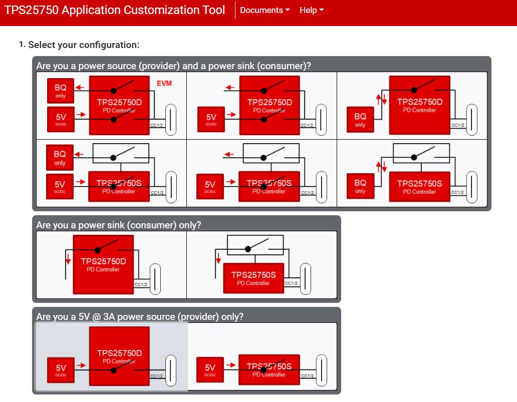 Figure 5-6 Provider Only - 5 V at 3
A
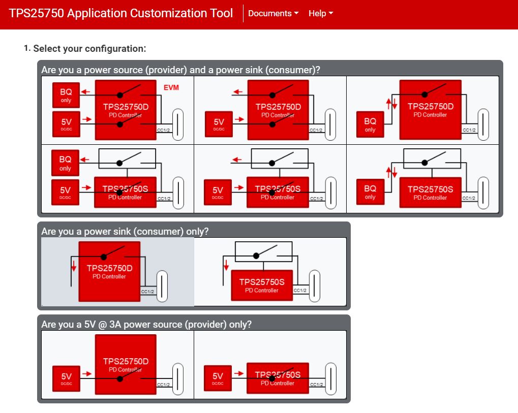 Figure 5-7 Sink Only Application
6 Schematic
The TPS25750 schematics are shown below.
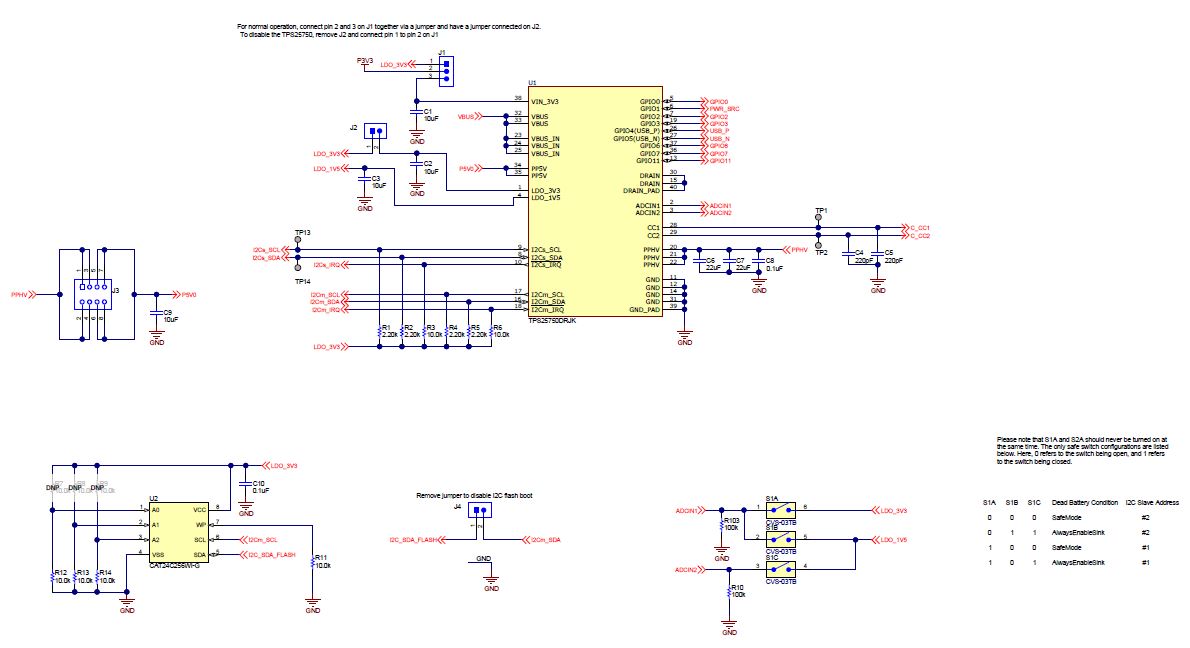 Figure 6-1 TPS25750
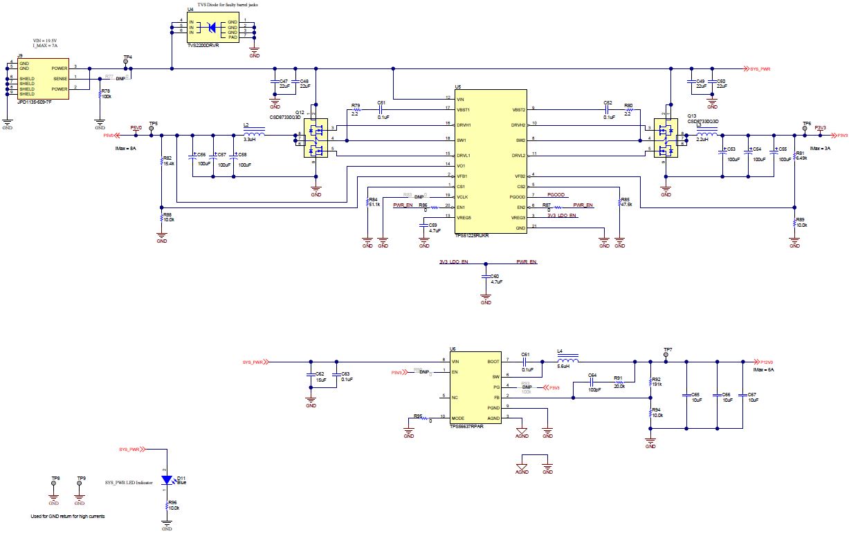 Figure 6-2 TPS51225 - 5 V, and 3.3-V Supply, TPS56637 -
12-V Supply
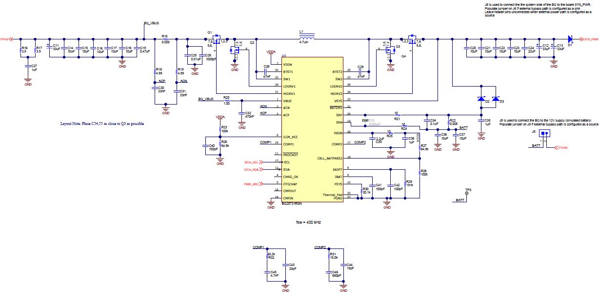 Figure 6-3 BQ25731 - Battery Charger
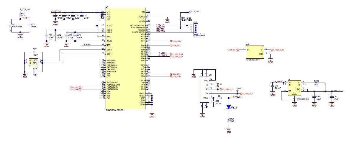 Figure 6-4 TM4C123GH6PMTR - USB2.0 to I2C Programmer
 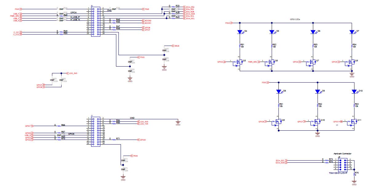 Figure 6-5 Debug Header and Status LED
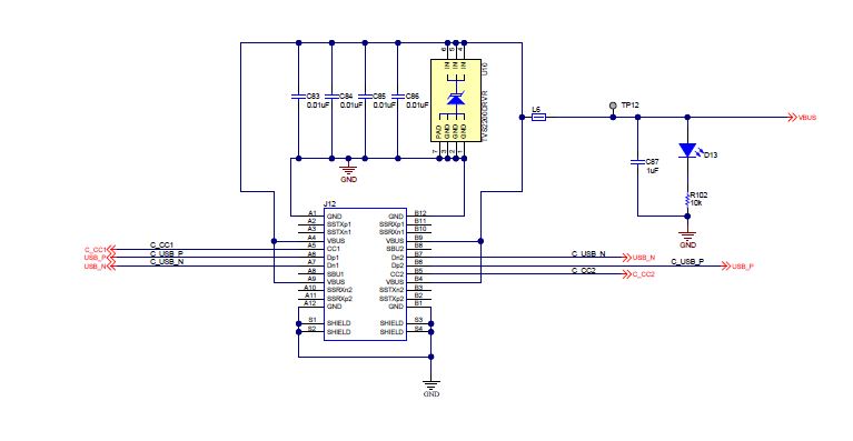 Figure 6-6 USB Type-C Port
7 Bill of Materials
The TPS25750EVM Bill of Materials (BOM) table is shown below:
| Designator | Quantity | Value | Description | PackageReference | PartNumber | Manufacturer |
|---|---|---|---|---|---|---|
| !PCB1 | 1 | Printed Circuit Board | PSIL138 | Any | ||
| C1, C2, C3 | 3 | 10 uF | CAP, CERM, 10 uF, 10 V, +/- 20%, X5R, 0402 | 0402 | CL05A106MP5NUNC | Samsung Electro-Mechanics |
| C4, C5 | 2 | 220 pF | CAP, CERM, 220 pF, 50 V, +/- 10%, X7R, AEC-Q200 Grade 1, 0201 | 0201 | CGA1A2X7R1H221K030BA | TDK |
| C6, C7, C24, C47, C48, C49, C50 | 7 | 22 uF | CAP, CERM, 22 uF, 35 V, +/- 20%, X5R, 0805 | 0805 | C2012X5R1V226M125AC | TDK |
| C8, C10, C34, C51, C52, C63 | 6 | 0.1uF | CAP, CERM, 0.1 uF, 35 V, +/- 10%, X5R, 0402 | 0402 | GMK105BJ104KV-F | Taiyo Yuden |
| C9 | 1 | 10 uF | CAP, CERM, 10 uF, 25 V, +/- 20%, X5R, 0603 | 0603 | GRM188R61E106MA73D | MuRata |
| C11, C12, C13 | 3 | 33 uF | CAP, TA, 33 uF, 35 V, +/- 20%, 0.065 ohm, SMD | 7343-31 | T521D336M035ATE065 | Kemet |
| C14, C15, C16, C17, C18, C20, C21, C22, C23, C36, C37 | 11 | 10 uF | CAP, CERM, 10 uF, 25 V, +/- 10%, X5R, 0805 | 0805 | GRM21BR61E106KA73L | MuRata |
| C19 | 1 | 0.47 uF | CAP, CERM, 0.47 uF, 16 V, +/- 10%, X7R, 0805 | 0805 | C0805C474K4RACTU | Kemet |
| C25, C79, C82, C83, C84, C85, C86 | 7 | 0.01 uF | CAP, CERM, 0.01 uF, 50 V, +/- 5%, X7R, 0402 | 0402 | C0402C103J5RACTU | Kemet |
| C26 | 1 | 1000 pF | CAP, CERM, 1000 pF, 50 V, +/- 10%, X7R, 0402 | 0402 | C0402C102K5RACTU | Kemet |
| C27, C35, C38, C87 | 4 | 1 uF | CAP, CERM, 1 uF, 35 V, +/- 10%, X5R, 0402 | 0402 | GRM155R6YA105KE11D | MuRata |
| C28, C29 | 2 | 0.047 uF | CAP, CERM, 0.047 uF, 25 V, +/- 5%, X7R, 0603 | 0603 | 06033C473JAT2A | AVX |
| C30, C31 | 2 | 0.033 uF | CAP, CERM, 0.033 uF, 25 V, +/- 5%, X7R, 0603 | 0603 | C0603C333J3RACTU | Kemet |
| C32 | 1 | 0.47 uF | CAP, CERM, 0.47 uF, 50 V, +/- 10%, X7R, 0603 | 0603 | UMK107B7474KA-TR | Taiyo Yuden |
| C39 | 1 | 2.2 uF | CAP, CERM, 2.2 uF, 35 V, +/- 10%, X5R, 0603 | 0603 | GRM188R6YA225KA12D | MuRata |
| C40, C41, C42 | 3 | 100 pF | CAP, CERM, 100 pF, 50 V, +/- 5%, C0G/NP0, 0603 | 0603 | 06035A101JAT2A | AVX |
| C43 | 1 | 33 pF | CAP, CERM, 33 pF, 50 V, +/- 5%, C0G/NP0, 0402 | 0402 | C1005C0G1H330J050BA | TDK |
| C44 | 1 | 15 pF | CAP, CERM, 15 pF, 50 V, +/- 5%, C0G/NP0, 0402 | 0402 | CC0402JRNPO9BN150 | Yageo America |
| C45 | 1 | 4700 pF | CAP, CERM, 4700 pF, 50 V, +/- 5%, X7R, 0603 | 0603 | C0603C472J5RACTU | Kemet |
| C46 | 1 | 680 pF | CAP, CERM, 680 pF, 50 V,+/- 1%, C0G/NP0, AEC-Q200 Grade 1, 0402 | 0402 | GCM1555C1H681FA16D | MuRata |
| C53, C54, C55, C56, C57, C58 | 6 | 100 uF | CAP, TA, 100 uF, 6.3 V, +/- 20%, 0.015 ohm, SMD | 3528-21 | T520B107M006ATE015 | Kemet |
| C59, C60 | 2 | 4.7 uF | CAP, CERM, 4.7 uF, 6.3 V, +/- 20%, X5R, 0402 | 0402 | GRM155R60J475ME87D | MuRata |
| C61 | 1 | 0.1 uF | CAP, CERM, 0.1 uF, 16 V, +/- 10%, X7R, 0402 | 0402 | 885012205037 | Wurth Elektronik |
| C62 | 1 | 15 uF | CAP, CERM, 15 uF, 35 V, +/- 20%, X5R, 0805 | 0805 | C2012X5R1V156M125AC | TDK |
| C64 | 1 | 100 pF | CAP, CERM, 100 pF, 25 V, +/- 10%, X7R, 0201 | 0201 | GRM033R71E101KA01D | MuRata |
| C65, C66, C67, C80, C81 | 5 | 10 uF | CAP, CERM, 10 uF, 25 V, +/- 10%, X7R, 1206 | 1206 | GRM31CR71E106KA12L | MuRata |
| C68, C69, C70, C71, C74, C76 | 6 | 0.1 uF | CAP, CERM, 0.1 uF, 10 V, +/- 10%, X5R, 0201 | 0201 | CL03A104KP3NNNC | Samsung Electro-Mechanics |
| C72 | 1 | 180 pF | CAP, CERM, 180 pF, 25 V, +/- 10%, X7R, 0201 | 0201 | GRM033R71E181KA01D | MuRata |
| C73, C75 | 2 | 4.7 uF | CAP, CERM, 4.7 uF, 6.3 V, +/- 20%, X5R, 0201 | 0201 | GRM035R60J475ME15D | MuRata |
| C77, C78 | 2 | 10 pF | CAP, CERM, 10 pF, 16 V,+/- 10%, C0G, 0402 | 0402 | C0402C100K4GACTU | Kemet |
| D1, D2, D3 | 3 | 40 V | Diode, Schottky, 40 V, 5 A, AEC-Q101, SOD-128 | SOD-128 | PMEG4050EP,115 | Nexperia |
| D4, D5, D6, D7, D8, D9, D10, D12, D13 | 9 | White | LED, White, SMD | 0402, White | LW QH8G-Q2S2-3K5L-1 | OSRAM |
| D11 | 1 | Blue | LED, Blue, SMD | LED_0603 | 150060BS75000 | Wurth Elektronik |
| J1 | 1 | Header, 100 mil, 3 x 1, Tin, TH | Header, 3 PIN, 100mil, Tin | PEC03SAAN | Sullins Connector Solutions | |
| J2, J4, J5 | 3 | Header, 100 mil, 2 x 1, Gold, TH | Sullins 100 mil, 1 x 2, 230 mil above insulator | PBC02SAAN | Sullins Connector Solutions | |
| J3 | 1 | Receptacle, 2.54 mm, 4 x 2, Gold, TH | Receptacle, 2.54 mm, 4 x 2, TH | SSQ-104-03-G-D | Samtec | |
| J6, J7 | 2 | Receptacle, 12 x 2, 2.54 mm, Gold, SMT | Receptacle, 12 x 2, 2.54 mm, SMT | SSW-112-22-G-D-VS | Samtec | |
| J8 | 1 | Header, 2.54 mm, 5 x 2, Gold, SMT | Header, 2.54 mm, 5 x 2, SMT | TSM-105-01-L-DV-P | Samtec | |
| J9 | 1 | Connector, DC Power Jack, R/A, 3 Pos, TH | Power connector | JPD1135-509-7F | Foxconn | |
| J10 | 1 | Header, 2.54 mm, 4 x 1, Gold, SMT | Header, 2.54 mm, 4 x 1, SMT | 61000418221 | Wurth Elektronik | |
| J11 | 1 | Connector, Receptacle, Micro-USB Type AB, R/A, Bottom Mount SMT | Connector, USB Micro AB | DX4R205JJAR1800 | JAE Electronics | |
| J12 | 1 | Receptacle, USB 3.1 Type C, R/A, Gold, SMT | Receptacle, USB 3.1 Type C, R/A, SMT | DX07S024JJ2R1300 | JAE Electronics | |
| L1 | 1 | 4.7 uH | Inductor, Shielded, Composite, 4.7 uH, 13.6 A, 0.01 ohm, SMD | 7.2 x 7 x 7.5 mm | XAL7070-472MEB | Coilcraft |
| L2 | 1 | 3.3 uH | Inductor, Shielded Drum Core, Superflux, 3.3 uH, 8 A, 0.0096 ohm, SMD | 6.9 x 4.8 x 6.9 mm | 744314330 | Wurth Elektronik |
| L3 | 1 | 2.2 uH | Inductor, Shielded Drum Core, Powdered Iron, 2.2 uH, 3.25 A, 0.051 ohm, SMD | 4.45 x 1.8 x 4.06 mm | 74437324022 | Wurth Elektronik |
| L4 | 1 | 5.6 uH | Inductor, Shielded, Composite, 5.6 uH, 11.4 A, 0.01 ohm, SMD | 7.2 x 7 x 7.5 mm | XAL7070-562MEB | Coilcraft |
| L5 | 1 | 26 ohm | Ferrite Bead, 26 ohm @ 100 MHz, 6 A, 0603 | 0603 | BLM18SG260TN1D | MuRata |
| L6 | 1 | 21 ohm | Ferrite Bead, 21 ohm @ 100 MHz, 6 A, 0805 | 0805 | FBMJ2125HM210NT | Taiyo Yuden |
| Q1, Q2, Q3, Q4 | 4 | 30 V | MOSFET, N-CH, 30 V, 14 A, DNH0008A (VSONP-8) | DNH0008A | CSD17578Q3A | Texas Instruments |
| Q5, Q6, Q7, Q8, Q9, Q10, Q11 | 7 | 20 V | MOSFET, N-CH, 20 V, 0.5 A, YJM0003A (PICOSTAR-3) | YJM0003A | CSD15380F3 | Texas Instruments |
| Q12, Q13 | 2 | 30 V | MOSFET, 2-CH, N-CH, 30 V, 20 A, DQZ0008A (LSON-CLIP-8) | DQZ0008A | CSD87330Q3D | Texas Instruments |
| R1, R2, R4, R5 | 4 | 2.20 k | RES, 2.20 k, 1%, 0.05 W, 0201 | 0201 | CRCW02012K20FKED | Vishay-Dale |
| R3, R6, R11, R12, R13, R14 | 6 | 10.0 k | RES, 10.0 k, 1%, 0.05 W, 0201 | 0201 | CRCW020110K0FKED | Vishay-Dale |
| R10, R103 | 2 | 100 k | RES, 100 k, 1%, 0.063 W, AEC-Q200 Grade 0, 0402 | 0402 | RMCF0402FT100K | Stackpole Electronics Inc |
| R15, R22 | 2 | 0.005 | RES, 0.005, 1%, 1 W, AEC-Q200 Grade 0, 1206 | 1206 | CRF1206-FZ-R005ELF | Bourns |
| R16, R17 | 2 | 3.9 | RES, 3.9, 5%, 0.25 W, AEC-Q200 Grade 0, 1206 | 1206 | CRCW12063R90JNEA | Vishay-Dale |
| R18, R19 | 2 | 4.99 | RES, 4.99, 1%, 0.1 W, AEC-Q200 Grade 0, 0603 | 0603 | CRCW06034R99FKEA | Vishay-Dale |
| R20 | 1 | 1.00 | RES, 1.00, 1%, 0.1 W, 0603 | 0603 | CRCW06031R00FKEA | Vishay-Dale |
| R21, R24, R25 | 3 | 10 | RES, 10, 5%, 0.1 W, AEC-Q200 Grade 0, 0603 | 0603 | CRCW060310R0JNEA | Vishay-Dale |
| R23, R28 | 2 | 100 k | RES, 100 k, 1%, 0.1 W, 0603 | 0603 | RC0603FR-07100KL | Yageo America |
| R26, R27 | 2 | 64.9 k | RES, 64.9 k, 1%, 0.1 W, 0603 | 0603 | RC0603FR-0764K9L | Yageo America |
| R29 | 1 | 191 k | RES, 191 k, 1%, 0.1 W, 0603 | 0603 | CRCW0603191KFKEA | Vishay-Dale |
| R30 | 1 | 30.1 k | RES, 30.1 k, 1%, 0.1 W, AEC-Q200 Grade 0, 0603 | 0603 | CRCW060330K1FKEA | Vishay-Dale |
| R31 | 1 | 15.0 k | RES, 15.0 k, 1%, 0.063 W, 0402 | 0402 | CRCW040215K0FKED | Vishay-Dale |
| R32 | 1 | 40.2 k | RES, 40.2 k, 1%, 0.063 W, AEC-Q200 Grade 0, 0402 | 0402 | CRCW040240K2FKED | Vishay-Dale |
| R33, R39, R40, R43, R45, R46, R47, R48, R49, R50, R64, R65, R66, R67, R69, R70, R71, R73, R74, R76, R86, R87 | 22 | 0 | RES, 0, 5%, 0.05 W, 0201 | 0201 | CRCW02010000Z0ED | Vishay-Dale |
| R51, R52, R53, R54, R61, R62, R63, R102 | 8 | 10 k | RES, 10 k, 5%, 0.063 W, AEC-Q200 Grade 0, 0402 | 0402 | CRCW040210K0JNED | Vishay-Dale |
| R78 | 1 | 100 k | RES, 100 k, 1%, 0.063 W, AEC-Q200 Grade 0, 0402 | 0402 | CRCW0402100KFKED | Vishay-Dale |
| R79, R80 | 2 | 2.2 | RES, 2.2, 5%, 0.063 W, AEC-Q200 Grade 0, 0402 | 0402 | CRCW04022R20JNED | Vishay-Dale |
| R81 | 1 | 6.49 k | RES, 6.49 k, 1%, 0.063 W, AEC-Q200 Grade 0, 0402 | 0402 | CRCW04026K49FKED | Vishay-Dale |
| R82 | 1 | 15.4 k | RES, 15.4 k, 1%, 0.063 W, AEC-Q200 Grade 0, 0402 | 0402 | CRCW040215K4FKED | Vishay-Dale |
| R84 | 1 | 51.1 k | RES, 51.1 k, 1%, 0.063 W, AEC-Q200 Grade 0, 0402 | 0402 | CRCW040251K1FKED | Vishay-Dale |
| R85 | 1 | 47.5 k | RES, 47.5 k, 1%, 0.063 W, AEC-Q200 Grade 0, 0402 | 0402 | CRCW040247K5FKED | Vishay-Dale |
| R88, R89, R96, R98, R99, R101 | 6 | 10.0 k | RES, 10.0 k, 1%, 0.063 W, AEC-Q200 Grade 0, 0402 | 0402 | CRCW040210K0FKED | Vishay-Dale |
| R91 | 1 | 20.0 k | RES, 20.0 k, 1%, 0.063 W, AEC-Q200 Grade 0, 0402 | 0402 | CRCW040220K0FKED | Vishay-Dale |
| R92 | 1 | 191 k | RES, 191 k, 1%, 0.063 W, AEC-Q200 Grade 0, 0402 | 0402 | CRCW0402191KFKED | Vishay-Dale |
| R94 | 1 | 10.0 k | RES, 10.0 k, 1%, 0.05 W, 0201 | 0201 | RC0201FR-0710KL | Yageo America |
| R95 | 1 | 0 | RES, 0, 5%, 0.063 W, AEC-Q200 Grade 0, 0402 | 0402 | CRCW04020000Z0ED | Vishay-Dale |
|
R97 |
1 |
10.2 k | RES, 10.2 k, 1%, 0.05 W, 0201 | 0201 | RC0201FR-0710K2L | Yageo America |
| R100 | 1 | 249 k | RES, 249 k, 1%, 0.1 W, 0603 | 0603 | RC0603FR-07249KL | Yageo |
| S1 | 1 | DIP Switch, SPST, 3Pos, Slide, SMT | SW, 4.7 x 1.45 x 4 mm | CVS-03TB | Copal Electronics | |
| S2 | 1 | SWITCH TACTILE SPST-NO 0.05 A 12 V | 3 x 1.6 x 2.5 mm | B3U-1000P | Omron Electronic Components | |
| SH-J1, SH-J2, SH-J3, SH-J4, SH-J5, SH-J6, SH-J7 | 7 | Shunt, 2.54 mm, Gold, Black | Shunt, 2.54 mm, Black | 60900213421 | Wurth Elektronik | |
| TP1, TP2, TP3, TP4, TP5, TP6, TP7, TP8, TP9, TP12, TP13, TP14 | 12 | Test Point, Miniature, SMT | Test Point, Miniature, SMT | 5019 | Keystone | |
| U1 | 1 | USB Type-C and USB PD Controller with Integrated Power Switches Optimized for Power Applications | VQFN32 | TPS25750DRJK | Texas Instruments | |
| U2 | 1 | 256 kb I2C CMOS Serial EEPROM, SOIC-8 | SOIC-8 | CAT24C256WI-G | ON Semiconductor | |
| U3 | 1 | No Description | WQFN32 | BQ25731RSN | Texas Instruments | |
| U4, U10 | 2 | 22-V Precision Surge Protection Clamp, DRV0006A (WSON-6) | DRV0006A | TVS2200DRVR | Texas Instruments | |
| U5 | 1 | Dual Synchronous Step-Down Controller with 5-V and 3.3-V LDOs, RUK0020B (WQFN-20) | RUK0020B | TPS51225RUKR | Texas Instruments | |
| U6 | 1 | 4.5-V to 28-V Input, 6-A Synchronous Buck Converter with ULQ-mode, RPA0010A (VQFN-HR-10) | RPA0010A | TPS56637RPAR | Texas Instruments | |
| U7 | 1 | Tiva C Series Microcontroller, 256 KB Flash, 32 KB SRAM, 12 Bit, 12 Channels, -40 to 105 degC, 64-Pin LQFP (PM), Green (RoHS & no Sb/Br), Tape and Reel | PM0064A | TM4C123GH6PMTR | Texas Instruments | |
| U8 | 1 | ESD Protection Array for High-Speed Data Interfaces, 2 Channels, –40 to +85°C, 3-pin SOT (DRT), Green (RoHS & no Sb/Br) | DRT0003A | TPD2E009DRTR | Texas Instruments | |
| U9 | 1 | Single Output Fast Transient Response LDO, 1 A, Fixed 3.3 V Output, 2.7 to 10 V Input, with Low IQ, 8-pin SOIC (D), -40 to 125°C, Green (RoHS & no Sb/Br) | D0008A | TPS76833QDR | Texas Instruments | |
| Y1 | 1 | Crystal, 16 MHz, 8 pF, SMD | 3.2 x 0.75 x 2.5 mm | NX3225GA-16.000M-STD-CRG-1 | NDK | |
| C33 | 0 | 0.068 uF | CAP, CERM, 0.068 uF, 16 V, +/- 10%, X5R, 0402 | 0402 | GRM155R61C683KA88D | MuRata |
| FID1, FID2, FID3, FID4, FID5, FID6 | 0 | Fiducial mark. There is nothing to buy or mount. | N/A | N/A | N/A | |
| R7, R8, R9 | 0 | 10.0 k | RES, 10.0 k, 1%, 0.05 W, 0201 | 0201 | CRCW020110K0FKED | Vishay-Dale |
| R34, R35 | 0 | 0 | RES, 0, 5%, 0.063 W, 0402 | 0402 | CRCW04020000Z0ED | Vishay-Dale |
| R36, R37, R38, R41, R42, R44, R68 | 0 | 0 | RES, 0, 5%, 0.05 W, 0201 | 0201 | CRCW02010000Z0ED | Vishay-Dale |
| R55, R56, R57, R58, R72, R75 | 0 | 100 k | RES, 100 k, 1%, 0.1 W, 0603 | 0603 | CRCW0603100KFKEA | Vishay-Dale |
| R59, R60 | 0 | 3.83 k | RES, 3.83 k, 1%, 0.05 W, 0201 | 0201 | CRCW02013K83FKED | Vishay-Dale |
| R77, R83, R90 | 0 | 0 | RES, 0, 5%, 0.063 W, AEC-Q200 Grade 0, 0402 | 0402 | CRCW04020000Z0ED | Vishay-Dale |
| R93 | 0 | 100 k | RES, 100 k, 1%, 0.063 W, AEC-Q200 Grade 0, 0402 | 0402 | CRCW0402100KFKED | Vishay-Dale |