SBAA441 June 2020 ADS7066
1 TI Tech Note
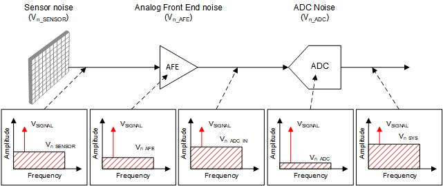
In an electronic system, the sensor, as well as all the active and passive components in the signal chain (resistors, amplifiers, reference, ADC) contribute to the overall noise in the measurement (Vn_SYS). Any one of these noise sources (Vn_SENSOR, Vn_AFE, or Vn_ADC) can be the dominant source of noise. To measure small change in sensor signal in presence of large random noise, the measurement system needs to have higher effective number of bits (ENOBSYS).
 Figure 1. Noise in Electronic System
 As illustrated in Figure 1, the noise at the ADC input (Vn_ADC_IN) is a combination of noise contributed by the sensor Vn_SENSOR and the noise contributed by the analog front end circuit used for signal conditioning Vn_AFE. If this noise present at the ADC input is greater than the noise contribution of the ADC (Vn_ADC_IN > Vn_ADC), then any improvement in Vn_ADC (achieved by using higher resolution ADC) will not improve ENOBSYS significantly, because Vn_ADC_IN will still remain the dominant source of noise.
In such cases, Vn_ADC_IN can be reduced by using lower noise components, but this may increase the power consumption, solution size, and cost of the system. Another approach to reduce Vn_ADC_IN is to use analog or digital filtering techniques.
One of the simplest forms of digital filtering is to compute the average of various ADC output samples. This document discusses how the programmable averaging filter in ADS7066 helps in boosting the resolution of the measurement or ENOBSYS.
Data Averaging to Improve Measurement Resolution
In most measurement systems, the noise contributions by the signal source (Vn_SENSOR), the analog front end (Vn_AFE), and the ADC (Vn_ADC) are uncorrelated, that is, each of them is white (random) noise. The primary benefit of calculating the average of various ADC output samples is to average this white (random) noise. When two uncorrelated signals (such as white noise) are summed together, they combine mathematically as a square root of the sum of the squares (RSS).
Assuming that signal and noise amplitude remains same, averaging of two samples increases the noise magnitude by a factor of 1.414, noise power by a factor of 2, signal magnitude by a factor of 2, and signal power by a factor of 4. The increase in SNR by averaging N samples is given by Equation 1.

By averaging two samples, SNR increases by 3 dB. For a DC signal, such as temperature or DC voltage input, ENOBSYS-DC is given by Equation 2

Therefore, averaging of multiple samples improves SNR (as shown in Equation 1) and ENOBSYS-DC (as shown in Equation 2).
For AC signals, ENOBSYS-AC is given by Equation 3.

SINAD can be expressed in terms of SNR and THD as shown in Equation 4.

Averaging N samples improves the SNR (as shown in Equation 1), however, the total harmonic distortion (THD) remains unaffected. Hence, the maximum achievable SINAD is often limited by the THD specification of the ADC.
Programmable Averaging Filters in ADS7066
The ADS7066 is an 8-channel, multiplexed, 16-bit, successive approximation register analog-to-digital converters (SAR ADC) with integrated reference. The eight channels can be independently configured as either analog inputs, digital inputs, or digital outputs.
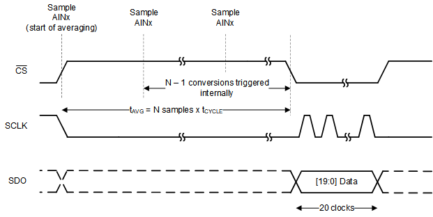
The ADS7066 features a built-in Programmable Averaging Filter that can be used to average 2, 4, 8, 16, 32, 64, or 128 samples for each analog input channel. This averaging filter configuration is common to all the analog input channels and can be selected enabled by programming the OSR[2:0] bits in the OSR_CFG register. Figure 2 shows that the averaging filter module output is 20 bits long (assuming CRC is disabled).
 Figure 2. Using Programmable Averaging Filter in ADS7066
 ADS7066 Performance Test Results
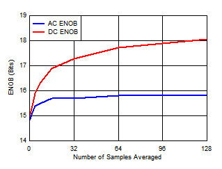
The ADS7066 specifies 91-dB SNR and -97-dB THD performance without any averaging. Table 1 and Figure 3 show the SNR, SINAD, and DC/AC ENOB for various settings of the Programmable Averaging Filter of ADS7066. The measurements are done with a 5 V external reference. The DC ENOB is measured when ADC input is 1 V DC while the AC ENOB is measured with 1 VPP, 2 kHz sine signal. By averaging 128 times, the SNR can reach 18-bit resolution (an increase of 3-bits), while SINAD can reach 15.8-bit resolution (an increase of 1-bit). The increase in SINAD is limited by the THD (-97 dB) specification.
 Figure 3. ENOB With ADS7066 Programmable Averaging Filter 175
 Conclusion
The programmable averaging filter in ADS7066 boosts the resolution of the measurements.
Table 1. Increase in Resolution With Programmable Averaging Filter
| NUMBER OF SAMPLES AVERAGED | INCREASE IN SNR (dB)
(Equation 1) |
EFFECTIVE SNR (dB) | EFFECTIVE SINAD (dB)
(Equation 4) |
AC ENOB (BITS)
(Equation 3) |
DC ENOB (BITS)
(Equation 2) |
|---|---|---|---|---|---|
| 0 | 0 | 91.74 | 90.61 | 14.8 | 14.95 |
| 2 | 2.67 | 94.41 | 92.50 | 15.1 | 15.39 |
| 4 | 5.70 | 97.44 | 94.20 | 15.4 | 15.89 |
| 8 | 8.28 | 100.02 | 95.24 | 15.5 | 16.32 |
| 16 | 11.68 | 103.42 | 96.11 | 15.7 | 16.89 |
| 32 | 14.07 | 105.81 | 96.46 | 15.7 | 17.28 |
| 64 | 16.72 | 108.46 | 96.70 | 15.8 | 17.72 |
| 128 | 18.66 | 110.40 | 96.81 | 15.8 | 18.05 |