ZHCU734A January 2017 – March 2020
3.2.1 Software Flow
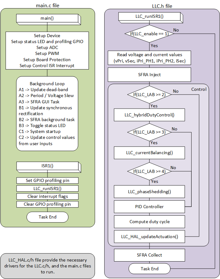
The software project makes use of the C-background and C-ISR framework. The project uses C-background code as the main supporting program for the application, which is responsible for all system management tasks, decision making, intelligence, and host interaction. The C-ISR code is executed inside a time critical interrupt service routine (ISR), and runs all the critical control code. This code includes ADC reading, control calculations, and PWM updates. The Control ISR portion of the C-ISR is executed at a fixed rate of 50 kHz using a spare PWM module timer.Figure 19 shows the general software flow for this project. Note the references to software frequency response analyzer (SFRA) library functions.
 Figure 19. TIDM-1001 - Software Flow
 Texas Instruments' SFRA library is designed to enable frequency response analysis on digitally controlled power converters using software alone, which enables performing frequency response analysis of the power converter with relative ease as no external connections or equipment is required. The optimized library can be used in high-frequency power conversion applications to identify the plant and the open-loop characteristics of a closed-loop power converter, which can be used to get stability information such as bandwidth, gain margin, and phase margin to evaluate the control loop performance. For more information, refer to the SFRA library documentation.
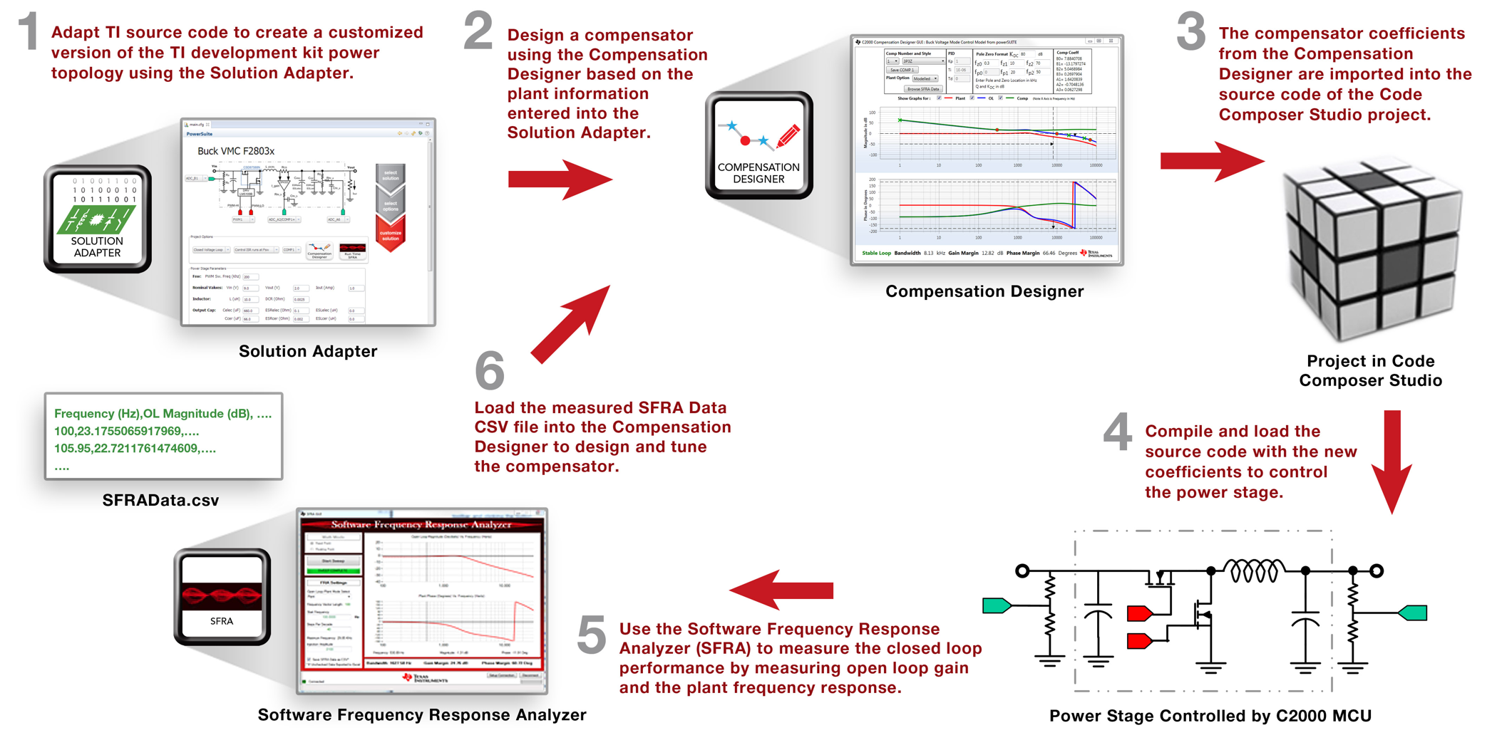
In addition to SFRA, this kit supports the use of other powerSUITE tools including the Compensation Designer and the Solution Adapter. These tools help users evaluate the complete system, adapt it for their end application, and tune it for improved performance. Figure 20 shows the typical process flow for designing and tuning such a system using the powerSUITE tools.
 Figure 20. Design Flow With powerSUITE
 The Solution Adapter tool allows users to adapt existing code examples from TI digital power application library and configure them to run on their custom digital power supply board that uses the same topology and similar resources. The GUI steps the user through the process of selecting the solution to adapt, selecting the relevant options for that solution, and customizing those options to adapt the software solution to the user's custom hardware design.
The Compensation Designer tool allows the design of different styles of compensators to achieve the desired closed loop performance, which can be done using the measured power stage or plant data from the SFRA Tool. The coefficients that must be programmed on the device are generated by the Compensation Designer and can be copied into the code directly. Note that the default software project uses a two-pole, two-zero control law and does not support three-pole, three-zero compensators. A PID controller is included as an option. Only the PI coefficients can be designed with Compensation Designer, but a user defined set of coefficients is defined in llc_user_settings.h and can be used to define a manually tuned PID controller. The PID Controller Tuning Guide provided in the documentation for the Digital Control Library provides guidance that can be used for this process.
The key framework C file used in this project is llc_main.c. This file is used to initialize, run, and manage the application. Driver code for the TMS320F280025C device is in llc_hal.c / llc_hal.h files. The llc.c / llc.h files have all the time-critical control code found in the ISR, as well as the other code specific to the power stage including phase shedding, current balancing, and SR enable / disable threshold. User configurable settings for the project are included in the llc_user_settings.h file. The llc_settings.h file is automatically generated by the powerSUITE GUI and if developing with powerSUITE enabled, any modifications to llc_settings.h will be overwritten when the project is built.
The modular structure makes it convenient to visualize and understand the complete system software flow. The structure also allows for easy use and for additions and deletions of various functionalities. This fact is amply demonstrated in this project by implementing an incremental lab approach, which is discussed in more detail in the Section 3.2.2.