ZHCU563B March 2015 – December 2018
7 Running the Single Chip Motor-Control Application With TwinCAT 3 EtherCAT Master on a PC
To test the single-chip motor-control application, use TwinCAT or another compatible EtherCAT master with CiA402 Drive profile support.
Additional details on TwinCAT configuration can be found at Configuring TwinCAT For TI EtherCAT Slave.
To use TI slave with TwinCAT, do the following:
- Install TwinCAT3. (A one-month evaluation is available for free download from TwinCAT3 Download.)
- Select the eXtended Automation Engineering (XAE) mode of installation
- Copy [EtherCAT SDK]\protocols\ethercat_slave\ecat_appl\esi\TI_ESC.xml to <Drive>:\TwinCAT\3.1\Config\Io\EtherCAT folder.
- Start the TwinCAT system manager.
- Create a new TwinCAT XAE project.
- Select New under the File menu option.
- Select Project.
- Select TwinCAT Project.
- Navigate to Options.
- Select Show Real-Time Ethernet Compatible Devices
- Install the TwinCAT RT Ethernet intermediate driver.
- Connect the CAT5 Ethernet cable from the TwinCAT PC to the EtherCAT IN/Port0 (J6) of the IDK. (If you have multiple IDKs in the chain, connect from the EtherCAT OUT/Port1 [J9] to the Port0 of the next IDK. For the last IDK in chain, leave Port1 open.)
- In Solution Explorer, go to a new TwinCAT project.
- Select I/O.
- Right-click Device1 (EtherCAT).
- If Scan Boxes is grayed out, select Restart TwinCAT (Config Mode).
- If running TwinCAT 2 on Windows XP, select Device1 (EtherCAT)
- Navigate to TwinCAT.
- Select Reload Devices.
- If running TwinCAT 3 on Windows 7, select Device1 (EtherCAT).
- Navigate to TwinCAT.
- Select Reload Devices.
NOTE
TI Box n (ti-esc) is automatically detected.
- If running TwinCAT 2 on Windows XP, select Device1 (EtherCAT)
- Select Scan Boxes.
- When asked to load I/O devices, select Yes.
- When asked to confirm to activate free run, select Yes. (TI ESC will enter OP mode.)
- The application turns on the digital out LEDs 1 through 8. (This indicates that slave is on and in INIT state.)
- To display the EtherCAT device state, select a device.
- Select the Online tab. (The device should be in the OP state with no lost frames or Tx / Rx / Errors.)
- Right-click on MOTION → Select "Add new Item..."
- Select "NC/PTP NCI Configuration" to put "NC-Task 1 SAF" under MOTION.
- Right-click on "MOTION→ NC-Task 1 SAF→ Axes" and select Add new Item...
- Select "Continuous Axis" Type and Click on OK. This adds "Axis 1" under Axes.
- Go to the Settings Tab under Axis 1. Select "CANopen DS402/Profile MDP 742" as the Axis Type.
- Now the Device variables must be linked to the axis variables, as shown in Table 1.
- Update the Operation Mode of the Device to DC-Synchron: Box 1 → DC Tab → Operation Mode → Select DC-Synchron.
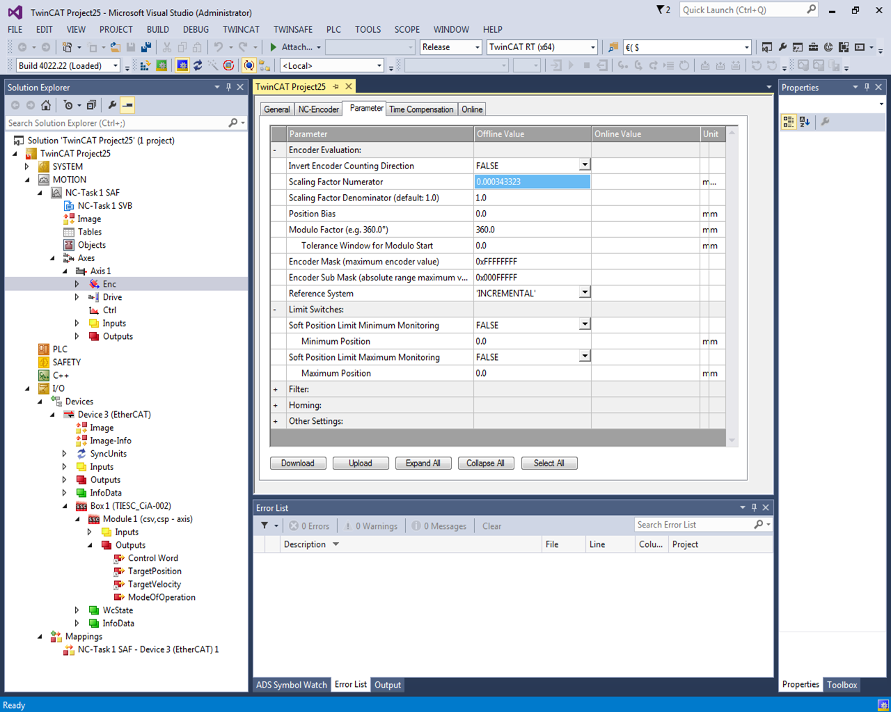
- Update the Encoder Scaling Factor: Axis 1 → Enc → Parameter Tab → Set value of "Scaling Factor Numerator" to "0.000343323".
- Start the TwinCAT System in Run Mode. Click on "Activate Configuration" to do the same.
- The default module added in the Box is the combined "csv, csp - axis". To select either csv or csp, the Box 1 → Module 1 → Outputs → ModeOfOperation variable must be set..
- To enable the axis control, Select "Online" Tab under "Axis 1". Click on Set button under Enabling section. Tick all the options and set Override % to 100.
- The setup is now complete. To test the Motor Control, set the Target Position and Target Velocity. Click on Start Button (F5). The Motor turns and stops at the specified target position.
NOTE
TI recommends to using a NIC-compatible card listed at Supported Network Controller by Beckhoff Ethernet Driver. Check that the ethernet adapter is listed under Installed and ready to use devices before run running the TwinCAT demonstration.
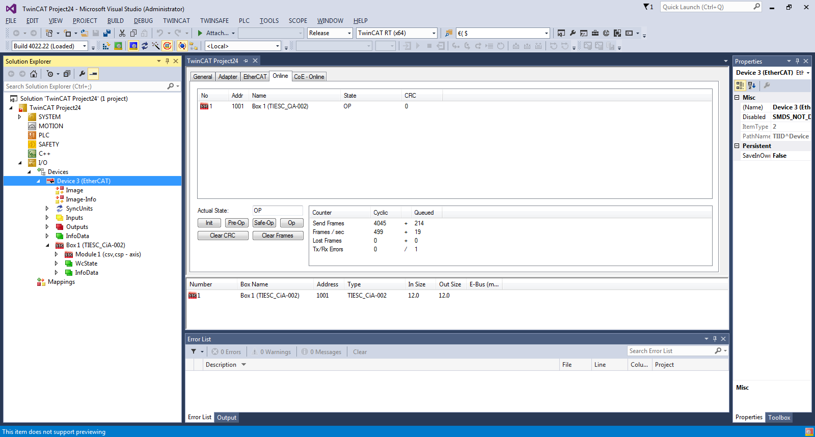
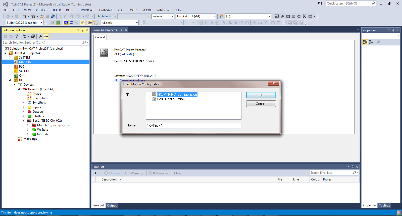 Figure 7. NC/PTP NCI Configuration
 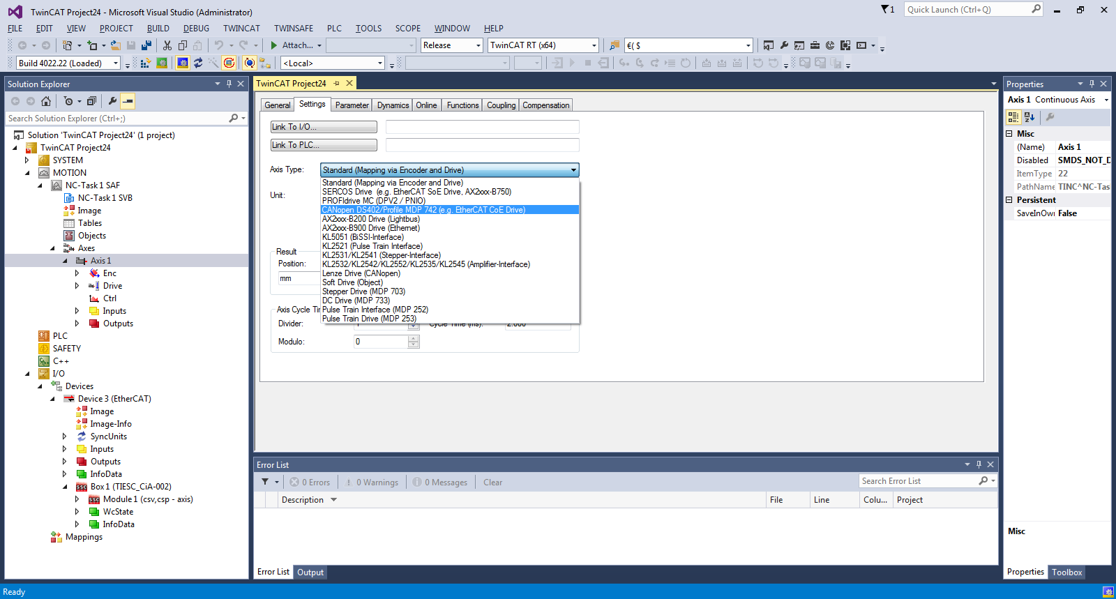 Figure 8. Select Axis Type
 Table 1. Axis Variables
| Device | NC Axis |
|---|---|
| Box1 → Module 1→ Inputs → Status Word | Axis 1 → Drive → In → nState1 + nState2 |
| Box1 → Module 1→ Inputs → ActualPosition | Axis 1 → Enc → In → nDataIn1 |
| Box1 → Module 1→ Outputs → Control Word | Axis 1 → Drive → Out → nCtrl1 + nCtrl2 |
| Box1 → Module 1→ Outputs → TargetPosition (required only in csp mode) | Axis 1 → Drive → Out → nDataOut1 |
| Box1 → Module 1→ Outputs → TargetVelocity (required only in csv mode) | Axis 1 → Drive → Out → nDataOut2 |
For the Status Word and Control Word, continuous process data mapping is required. This can be performed in the linking window (for example, the Status Word link window in Figure 9). Enable “All Types”, “Continuous” and select the desired variables. TwinCAT maps “nState1” to the low byte and “nState2” to the high byte of the Status Word.
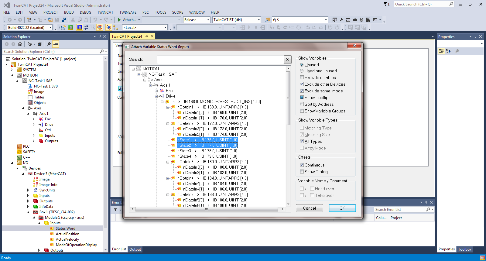 Figure 9. Status Word Link Window
 The formula to calculate the Scaling Factor is enc.scaling = (mm/rev)/encoder resolution. In this application, the encoder resolution is set to 2^20 = 1048576. Taking 360 mm per rev. The scaling factor is calculated as (360/1048576) = 0.000343323.
(Only required for csv mode) Update the Output Velocity Scaling Factor : Axis 1 → Drive → Parameter Tab → Position and Velocity Scaling → Set value of "Output Scaling Factor (Velocity)" to "7500.007152564"
The formula to calculate the Output Velocity Scaling Factor is velo.scaling = (2^20 / encoder resolution) * (velo resolution / 139.81). In this application, the encoder and velocity resolution are both set to 2^20 - 1048576. Therefore, the scaling factor is calculated as (2^20/2^20) * (2^20/139.81) = 7500.007152564. The encoder and velocity resolution are set as macros in the the patched cia402appl.c.
#define TWINCAT_SINGLE_TURN_RES pow(2, 20)
#define TWINCAT_VELOCITY_RES pow(2, 20)
Updating these values will also require updating the scaling factors accordingly.
The formula to calculated the scaling factor is described in the EtherCAT Slave Stack Code Application Note ET9300

For csp → ModeOfOperation = 8
For csv → ModeOfOperation = 9
Refer to the ETG 6010 CiA402 Implementation Directive for details on the ModeOfOperation variable values.
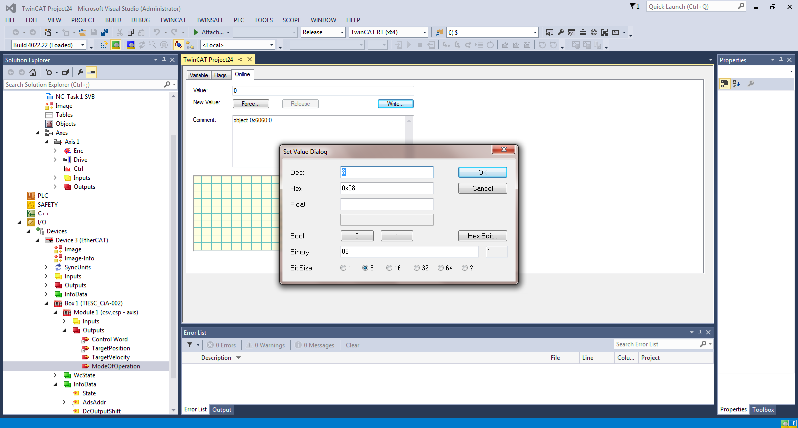 Figure 11. Set Mode of Operation
 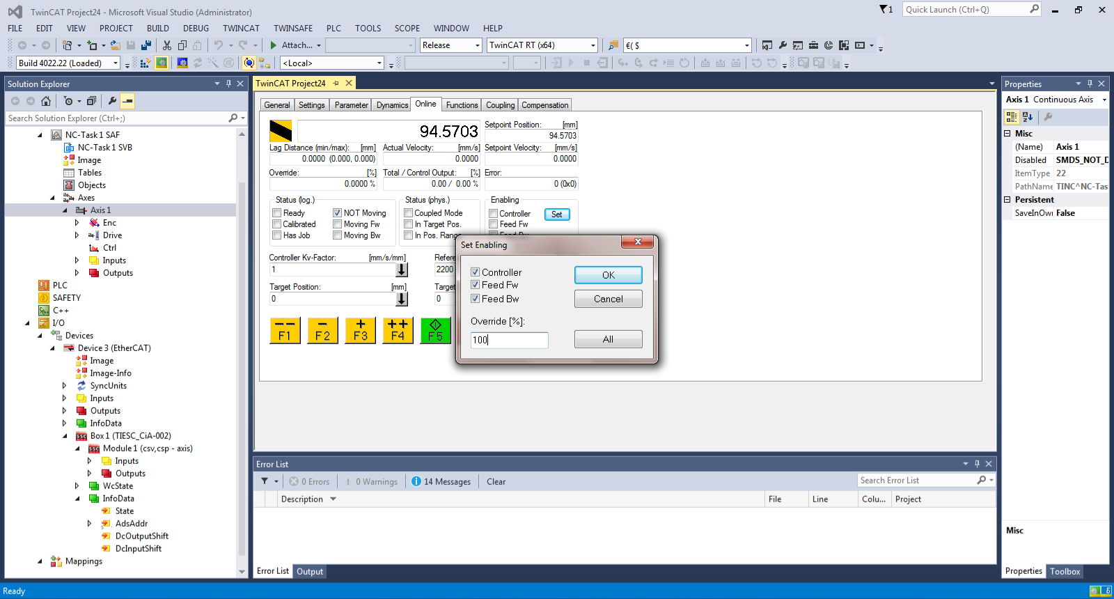 Figure 12. Enable Axis Control
 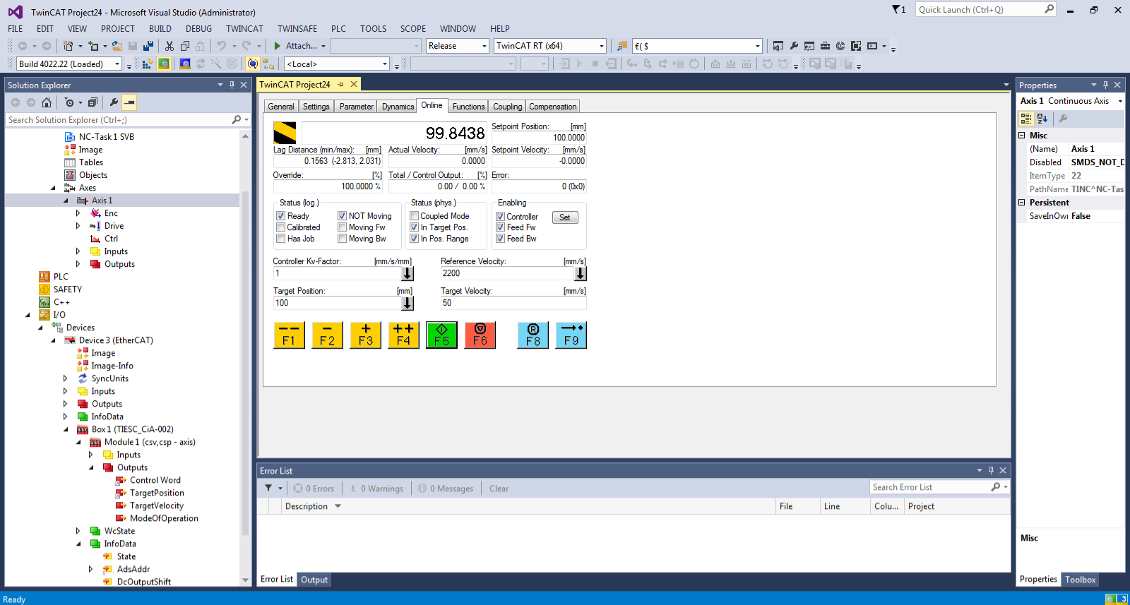 Figure 13. Setup Complete