• Menu
  • Product
  • Email
  • PDF
  • Order now
  • TPS50601A-SP 耐辐射 3V 至 7V 输入、6A 同步降压转换器

    • ZHCSHX8D September   2017  – October 2019 TPS50601A-SP

      PRODUCTION DATA.  

  • CONTENTS
  • SEARCH
  • TPS50601A-SP 耐辐射 3V 至 7V 输入、6A 同步降压转换器
  1. 1 特性
    1.     VIN = PVIN = 5V 条件下的效率
  2. 2 应用
  3. 3 说明
  4. 4 修订历史记录
  5. 5 Pin Configuration and Functions
    1.     Pin Functions
  6. 6 Specifications
    1. 6.1 Absolute Maximum Ratings
    2. 6.2 ESD Ratings
    3. 6.3 Recommended Operating Conditions
    4. 6.4 Thermal Information
    5. 6.5 Electrical Characteristics
    6. 6.6 Typical Characteristics
  7. 7 Detailed Description
    1. 7.1 Overview
    2. 7.2 Functional Block Diagram
    3. 7.3 Feature Description
      1. 7.3.1  VIN and Power VIN Pins (VIN and PVIN)
      2. 7.3.2  Voltage Reference
      3. 7.3.3  Adjusting the Output Voltage
      4. 7.3.4  Safe Start-Up Into Prebiased Outputs
      5. 7.3.5  Error Amplifier
      6. 7.3.6  Slope Compensation
      7. 7.3.7  Enable and Adjust UVLO
      8. 7.3.8  Adjustable Switching Frequency and Synchronization (SYNC)
      9. 7.3.9  Slow Start (SS/TR)
      10. 7.3.10 Power Good (PWRGD)
      11. 7.3.11 Sequencing (SS/TR)
      12. 7.3.12 Output Overvoltage Protection (OVP)
      13. 7.3.13 Overcurrent Protection
        1. 7.3.13.1 High-Side MOSFET Overcurrent Protection
        2. 7.3.13.2 Low-Side MOSFET Overcurrent Protection
      14. 7.3.14 Thermal Shutdown
      15. 7.3.15 Turn-On Behavior
      16. 7.3.16 Small Signal Model for Frequency Compensation
    4. 7.4 Device Functional Modes
      1. 7.4.1 Fixed-Frequency PWM Control
      2. 7.4.2 Continuous Current Mode (CCM) Operation
  8. 8 Application and Implementation
    1. 8.1 Application Information
    2. 8.2 Typical Application
      1. 8.2.1 Design Requirements
      2. 8.2.2 Detailed Design Procedure
        1. 8.2.2.1 Operating Frequency
        2. 8.2.2.2 Output Inductor Selection
        3. 8.2.2.3 Output Capacitor Selection
        4. 8.2.2.4 Slow Start Capacitor Selection
        5. 8.2.2.5 Undervoltage Lockout (UVLO) Set Point
        6. 8.2.2.6 Output Voltage Feedback Resistor Selection
        7. 8.2.2.7 Compensation Component Selection
      3. 8.2.3 Parallel Operation
      4. 8.2.4 Application Curve
  9. 9 Power Supply Recommendations
  10. 10Layout
    1. 10.1 Layout Guidelines
    2. 10.2 Layout Example
  11. 11器件和文档支持
    1. 11.1 文档支持
      1. 11.1.1 相关文档
    2. 11.2 接收文档更新通知
    3. 11.3 社区资源
    4. 11.4 商标
    5. 11.5 静电放电警告
    6. 11.6 Glossary
  12. 12机械、封装和可订购信息
  13. 重要声明
search No matches found.
  • Full reading width
    • Full reading width
    • Comfortable reading width
    • Expanded reading width
  • Card for each section
  • Card with all content


DATA SHEET

TPS50601A-SP 耐辐射 3V 至 7V 输入、6A 同步降压转换器

本资源的原文使用英文撰写。 为方便起见,TI 提供了译文;由于翻译过程中可能使用了自动化工具,TI 不保证译文的准确性。 为确认准确性,请务必访问 ti.com 参考最新的英文版本(控制文档)。

1 特性

  • 5962-10221:
    • 耐辐射高达 100krad (Si) TID
    • 无低剂量率辐射损伤增强 (ELDRS) 100 krad (Si) – 10mrad(Si)/s
    • 单粒子锁定 (SEL) 对于
      LET 的抗扰度 = 75MeV-cm2/mg
    • SEB 和 SEGR 抗扰度可达到 75MeV-cm2/mg,提供 SOA 曲线
    • 提供 SET/SEFI 横截面图
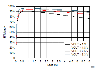
  • 峰值效率:96.6% (VO = 3.3V)
  • 集成了 58mΩ/50mΩ MOSFET
  • 电源轨:3 至 7V(输入电压)
  • 6A 最大输出电流
  • 灵活的开关频率选项:
    • 100kHz 至 1MHz 可调内部振荡器
    • 外部同步功能的频率范围:100kHz 至 1MHz
    • 可针对主/从应用将同步引脚配置为 500kHz
  • 0.804V ±1.5% 的电压基准过热、辐射以及线路和负载调节
  • 单调启动至预偏置输出
  • 通过外部电容器进行可调节的软启动
  • 用于电源定序的输入使能和电源正常输出
  • 针对欠压和过压问题的电源正常输出监控
  • 可调节输入欠压锁定 (UVLO)
  • 20 引脚超小型耐热增强型陶瓷扁平封装 (HKH),适用于太空 应用
  • VIN = PVIN = 5V 条件下的效率

    TPS50601A-SP D001_SLVSDF5.gif

2 应用

  • 用于 FPGA、微控制器、数据转换器和 ASIC 的太空卫星负载点电源
  • 航天卫星有效载荷
  • 耐辐射 应用
  • 支持军用(–55°C 至 125°C)温度范围
  • 可提供工程评估 (/EM) 样品

3 说明

TPS50601A-SP 是一款耐辐射的 7V、6A 同步降压转换器,此转换器具有高效率并集成了高侧和低侧 MOSFET,因此非常适合小型设计。通过电流模式控制减少组件数量,并通过高开关频率缩小电感器封装尺寸,从而进一步节省空间。此器件采用超小尺寸的热增强型 20 引脚陶瓷扁平封装。

输出电压启动斜坡由 SS/TR 引脚控制,可实现独立电源运行,或者跟踪状态下的运行。此外,正确配置启用与开漏电源正常引脚也可实现电源排序。此外,TPS50601A-SP 可配置为主/从模式,从而提供高达 12A 的输出电流。

高侧 FET 的逐周期电流限制可在过载情况下保护器件,并通过低侧电源限流防止电流失控,从而实现功能增强。此外,还提供可关闭低侧 MOSFET 的低侧吸收电流限值,以防止过多的反向电流。当芯片温度超过热关断温度时,热关断禁用此器件。

器件信息(1)

器件型号 等级 封装
5962-1022102VSC QMLV CFP (20)(4)
5962R1022102VSC RHA - 100krad (Si)
TPS50601AHKH/EM 工程评估(2)
5962R1022102V9A KGD RHA - 100krad (Si) 裸片(3)
  1. 如需了解所有可用封装,请参阅数据表末尾的可订购产品附录。
  2. 这些器件仅适用于工程评估。器件按照不合规的流程进行加工处理。这些器件不适用于质检、生产、辐射测试或飞行。这些零器件无法在 –55°C 至 125°C 的完整 MIL 额定温度范围内或运行寿命中保证其性能。
  3. 采用叠片封装的裸片。
  4. 重量 = 1.22g,四舍五入约为 ±10%

4 修订历史记录

Changes from C Revision (August 2018) to D Revision

  • 向器件信息 表中添加了注释:重量 = 1.22gGo
  • Changed the Pin Configuration imageGo
  • Changed SYNC out high level threshold MIN value From: 2 V To: VIN - 0.3 in the Electrical Characteristics tableGo
  • Deleted test Condition "Percent of program frequency" from SYNC in frequency range in the Electrical Characteristics tableGo
  • Changed "180° out of phase to the internal 500-kHz switching frequency." To: "180° in phase to the internal 500-kHz switching frequency." in the Description of Table 3Go
  • Changed "180° out of phase respect to the internal oscillator.." To: "180° in phase respect to the internal oscillator.." in the Parallel Operation sectionGo
  • Changed "(180° out of phase respect to the master device)." To: "(180° in phase respect to the master device).." in the Parallel Operation sectionGo

Changes from B Revision (June 2018) to C Revision

  • Replaced all coordinates in Bond Pad Coordinates in Microns table with corrected valuesGo

Changes from A Revision (March 2018) to B Revision

  • Added Bare Die Information tableGo
  • Added Bond Pad Coordinates in Microns tableGo

Changes from * Revision (September 2017) to A Revision

  • Changed 将器件状态从高级信息 更改为生产数据Go

5 Pin Configuration and Functions

HKH Package
20-Pin CFP
Bottom View

Pin Functions

PIN I/O DESCRIPTION
NO. NAME
1 GND — Return for control circuitry.(1)
2 EN I EN pin is internally pulled up allowing for the pin to be floated to enable the device. Adjust the input undervoltage lockout (UVLO) with two resistors.
3 RT I/O In internal oscillation mode, a resistor is connected between the RT pin and GND to set the switching frequency. Leaving this pin floating sets the internal switching frequency to 500 kHz.
4 SYNC I/O Optional 100-kHz to 1-MHz external system clock input.
5 VIN I Input power for the control circuitry of the switching regulator.
6 PVIN I Input power for the output stage of the switching regulator.
7
8 PGND — Return for low-side power MOSFET.
9
10
11 PH O Switch phase node.
12
13
14
15
16 REFCAP O Required 470-nF external capacitor for internal reference.
17 VSENSE I Inverting input of the gm error amplifier.
18 COMP I/O Error amplifier output and input to the output switch current comparator. Connect frequency compensation to this pin.
19 SS/TR I/O Slow-start and tracking. An external capacitor connected to this pin sets the internal voltage reference rise time. The voltage on this pin overrides the internal reference. It can be used for tracking and sequencing.
20 PWRGD O Power Good fault pin. Asserts low if output voltage is low due to thermal shutdown, dropout, overvoltage, or EN shutdown, or during slow start.
(1) GND (pin 1, analog ground) must be connected to PGND external to the package. Thermal pad must be connected to a heat dissipating layer. Thermal pad is internally connected to the seal ring and GND.

Table 1. Bare Die Information

DIE THICKNESS BACKSIDE FINISH BACKSIDE POTENTIAL BOND PAD METALLIZATION COMPOSITION BOND PAD THICKNESS
15 mils Silicon with backgrind Ground ALCU 1050 nm
TPS50601A-SP die_TPS50601A-SP_slvsdf5.png

Table 2. Bond Pad Coordinates in Microns

DESCRIPTION PAD NUMBER X MIN Y MIN X MAX Y MAX
AVSS 1 938.16 5098.41 1064.16 5224.41
AVSS 2 759.06 5098.41 885.06 5224.41
N/C 3 579.96 5098.41 705.96 5224.41
AVSS 4 400.86 5098.41 526.86 5224.41
AVSS 5 221.76 5098.41 347.76 5224.41
EN 6 38.7 4843.98 164.7 4969.98
RT 7 38.7 4115.43 164.7 4241.43
SYNC 8 38.7 3936.33 164.7 4062.33
VIN 9 55.89 3473.865 181.89 3599.865
VIN 10 55.89 3285.765 181.89 3411.765
VIN 11 55.89 3097.665 181.89 3223.665
VIN 12 55.89 2909.565 181.89 3035.565
PVIN 13 360.045 2468.025 486.045 2594.025
PVIN 14 500.805 2468.025 626.805 2594.025
PVIN 15 643.905 2468.025 769.905 2594.025
PVIN 16 782.505 2468.025 908.505 2594.025
PVIN 17 360.045 2312.595 486.045 2438.595
PVIN 18 500.805 2312.595 626.805 2438.595
PVIN 19 643.905 2312.595 769.905 2438.595
PVIN 20 782.505 2312.595 908.505 2438.595
PVIN 21 360.045 1868.265 486.045 1994.265
PVIN 22 500.805 1868.265 626.805 1994.265
PVIN 23 643.905 1868.265 769.905 1994.265
PVIN 24 782.505 1868.265 908.505 1994.265
PVIN 25 360.045 1712.835 486.045 1838.835
PVIN 26 500.805 1712.835 626.805 1838.835
PVIN 27 643.905 1712.835 769.905 1838.835
PVIN 28 782.505 1712.835 908.505 1838.835
PGND 29 360 1004.625 486 1130.625
PGND 30 498.6 1004.625 624.6 1130.625
PGND 31 637.2 1004.625 763.2 1130.625
PGND 32 775.8 1004.625 901.8 1130.625
PGND 33 360 863.955 486 989.955
PGND 34 498.6 863.955 624.6 989.955
PGND 35 637.2 863.955 763.2 989.955
PGND 36 775.8 863.955 901.8 989.955
PGND 37 360 384.525 486 510.525
PGND 38 360 243.855 486 369.855
PGND 39 503.1 243.855 629.1 369.855
PGND 40 503.1 384.525 629.1 510.525
PGND 41 641.7 243.855 767.7 369.855
PGND 42 641.7 384.525 767.7 510.525
PGND 43 775.8 243.855 901.8 369.855
PGND 44 775.8 384.525 901.8 510.525
PH 45 1239.66 97.425 1365.66 223.425
PH 46 1374.66 529.965 1500.66 655.965
PH 47 1378.26 97.425 1504.26 223.425
PH 48 1516.86 97.425 1642.86 223.425
PH 49 1657.26 97.425 1783.26 223.425
PH 50 1790.46 529.965 1916.46 655.965
PH 51 1651.86 529.965 1777.86 655.965
PH 52 1513.26 529.965 1639.26 655.965
PH 53 1790.46 718.515 1916.46 844.515
PH 54 1651.86 718.515 1777.86 844.515
PH 55 1513.26 718.515 1639.26 844.515
PH 56 1374.66 718.515 1500.66 844.515
PH 57 1790.46 1150.065 1916.46 1276.065
PH 58 1651.86 1150.065 1777.86 1276.065
PH 59 1513.26 1150.065 1639.26 1276.065
PH 60 1374.66 1150.065 1500.66 1276.065
PH 61 1795.365 1565.1 1921.365 1691.1
PH 62 1655.865 1565.1 1781.865 1691.1
PH 63 1515.465 1565.1 1641.465 1691.1
PH 64 1376.865 1565.1 1502.865 1691.1
PH 65 1795.365 2016 1921.365 2142
PH 66 1655.865 2016 1781.865 2142
PH 67 1515.465 2016 1641.465 2142
PH 68 1376.865 2016 1502.865 2142
PH 69 1795.365 2164.86 1921.365 2290.86
PH 70 1655.865 2164.86 1781.865 2290.86
PH 71 1515.465 2164.86 1641.465 2290.86
PH 72 1376.865 2164.86 1502.865 2290.86
PH 73 1795.365 2615.76 1921.365 2741.76
PH 74 1655.865 2615.76 1781.865 2741.76
PH 75 1515.465 2615.76 1641.465 2741.76
PH 76 1376.865 2615.76 1502.865 2741.76
REFCAP_NU 77 1933.245 3572.46 2059.245 3698.46
VSENSE 78 1933.245 3770.415 2059.245 3896.415
COMP 79 1933.245 3949.515 2059.245 4075.515
SS 80 1933.2 4149.135 2059.2 4275.135
PWRGD 81 1933.2 4292.325 2059.2 4418.325

6 Specifications

6.1 Absolute Maximum Ratings

over operating temperature (unless otherwise noted)(1)
MIN MAX UNIT
Input voltage VIN –0.3 7.5 V
PVIN –0.3 7.5
EN –0.3 5.5
VSENSE –0.3 3.3
COMP –0.3 3.3
PWRGD –0.3 5.5
SS/TR –0.3 5.5
RT –0.3 5.5
SYNC –0.3 7.5
Output voltage REFCAP –0.3 3.3 V
PH –1 7.5
PH 10-ns transient –3 7.5
Vdiff (GND to exposed thermal pad) –0.2 0.2 V
Source current PH Current limit Current limit A
RT ±100 µA
Sink current PH Current limit Current limit A
PVIN Current limit Current limit A
COMP ±200 µA
PWRGD –0.1 5 mA
Operating junction temperature –55 150 °C
Storage temperature, Tstg –65 150 °C
(1) Stresses beyond those listed under Absolute Maximum Ratings may cause permanent damage to the device. These are stress ratings only, which do not imply functional operation of the device at these or any other conditions beyond those indicated under Recommended Operating Conditions. Exposure to absolute-maximum-rated conditions for extended periods may affect device reliability.

6.2 ESD Ratings

VALUE UNIT
V(ESD) Electrostatic discharge Human-body model (HBM), per ANSI/ESDA/JEDEC JS-001, all pins(1) ±750 V
Charged-device model (CDM), per JEDEC specification JESD22-C101, all pins(2) ±1000
(1) JEDEC document JEP155 states that 500-V HBM allows safe manufacturing with a standard ESD control process.
(2) JEDEC document JEP157 states that 250-V CDM allows safe manufacturing with a standard ESD control process.


Texas Instruments

© Copyright 1995-2025 Texas Instruments Incorporated. All rights reserved.
Submit documentation feedback | IMPORTANT NOTICE | Trademarks | Privacy policy | Cookie policy | Terms of use | Terms of sale