• Menu
  • Product
  • Email
  • PDF
  • Order now
  • TPD2S701-Q1 汽车类 USB 双通道数据线路 VBUS 短路保护和 IEC ESD 保护

    • ZHCSGF6A April   2017  – July 2017 TPD2S701-Q1

      PRODUCTION DATA.  

  • CONTENTS
  • SEARCH
  • TPD2S701-Q1 汽车类 USB 双通道数据线路 VBUS 短路保护和 IEC ESD 保护
  1. 1 特性
  2. 2 应用
  3. 3 说明
  4. 4 修订历史
  5. 5 Pin Configuration and Functions
  6. 6 Specifications
    1. 6.1  Absolute Maximum Ratings
    2. 6.2  ESD Ratings—AEC Specification
    3. 6.3  ESD Ratings—IEC Specification
    4. 6.4  ESD Ratings—ISO Specification
    5. 6.5  Recommended Operating Conditions
    6. 6.6  Thermal Information
    7. 6.7  Electrical Characteristics
    8. 6.8  Power Supply and Supply Current Consumption Chracteristics
    9. 6.9  Timing Requirements
    10. 6.10 Typical Characteristics
  7. 7 Parameter Measurement Information
  8. 8 Detailed Description
    1. 8.1 Overview
    2. 8.2 Functional Block Diagram
    3. 8.3 Feature Description
      1. 8.3.1 OVP Operation
      2. 8.3.2 OVP Threshold
      3. 8.3.3 D± Clamping Voltage
    4. 8.4 Device Functional Modes
  9. 9 Application and Implementation
    1. 9.1 Application Information
    2. 9.2 Typical Application
      1. 9.2.1 Design Requirements
        1. 9.2.1.1 Device Operation
      2. 9.2.2 Detailed Design Procedure
        1. 9.2.2.1 VREF Operation
          1. 9.2.2.1.1 Mode 0
          2. 9.2.2.1.2 Mode 1
        2. 9.2.2.2 Mode 1 Enable Timing
      3. 9.2.3 Application Curves
  10. 10Power Supply Recommendations
    1. 10.1 VPWR Path
    2. 10.2 VREF Pin
  11. 11Layout
    1. 11.1 Layout Guidelines
    2. 11.2 Layout Example
  12. 12器件和文档支持
    1. 12.1 文档支持
      1. 12.1.1 相关文档
    2. 12.2 接收文档更新通知
    3. 12.3 社区资源
    4. 12.4 商标
    5. 12.5 静电放电警告
    6. 12.6 Glossary
  13. 13机械、封装和可订购信息
  14. 重要声明
search No matches found.
  • Full reading width
    • Full reading width
    • Comfortable reading width
    • Expanded reading width
  • Card for each section
  • Card with all content


DATA SHEET

TPD2S701-Q1 汽车类 USB 双通道数据线路 VBUS 短路保护和 IEC ESD 保护

本资源的原文使用英文撰写。 为方便起见,TI 提供了译文;由于翻译过程中可能使用了自动化工具,TI 不保证译文的准确性。 为确认准确性,请务必访问 ti.com 参考最新的英文版本(控制文档)。

1 特性

  • 符合 AEC-Q100 标准
    • –40°C 至 125°C 的工作温度范围
  • VD+ 和 VD– 上的 VBUS 短路保护
  • ESD 性能 VD+,VD–
    • ±8kV 接触放电(IEC 61000-4-2 和 ISO 10605 330pF,330Ω)
    • ±15kV 气隙放电(IEC 61000-4-2 和 ISO 10605 330pF,330Ω)
  • 高速数据开关(1GHz 带宽)
  • 只需要 5V 电源
  • 可调节 OVP 阈值
  • 快速过压响应时间(典型值 200ns)
  • 热关断特性
  • 集成输入使能和故障输出信号
  • 保证数据完整性的直通路由
    • 10 引脚 VSSOP 封装 (3mm × 3mm)
    • 10 引脚 QFN 封装 (2.5mm × 2.5mm)

2 应用

  • 终端设备
    • 音响主机
    • 后座娱乐系统
    • 远程信息处理
    • USB 集线器
    • 导航模块
    • 媒体接口
  • 接口
    • USB 2.0
    • USB 3.0

3 说明

TPD2S701-Q1 是一款用于汽车高速接口(如 USB 2.0)的双通道线路 VBUS 短路和 IEC61000-4-2 ESD 保护器件。TPD2S701-Q1 包含两个数据线路 nFET 开关。这些开关通过提供业界一流的带宽,实现最小的信号衰减,同时可保护内部系统电路(在 VD+ 和 VD– 引脚上),使其免受过压情况的损坏,从而确保安全的数据通信。

在这些引脚上,此器件可实现直流电高达 7V 的过压保护。这为 USB VBUS 轨的数据线路短路提供了充分保护。该过压保护电路提供业界最可靠的 VBUS 短路隔离,能在 200ns 内关闭数据开关,并保护上游电路免受有害电压和电流尖峰影响。

此外,TPD2S701-Q1 只需要 5V 的单一电源,这优化了电源树的大小和成本。该器件允许通过电阻分压器网络调整 OVP 阈值和钳位电路,为优化系统保护提供了一种简单且经济高效的方法(适用于任何收发器)。TPD2S701-Q1 还包括一个 FLT 引脚,该引脚会在器件出现过压状况时发出指示,并在过压状况消除后自动复位。

TPD2S701-Q1 还在 VD+ 和 VD– 引脚上集成了系统级别的 IEC 61000-4-2 和 ISO 10605 ESD 钳位,因此在应用中无需再配置高压、低电容的外部 TVS 钳位电路。

器件信息(1)

器件型号 封装 封装尺寸(标称值)
TPD2S701-Q1 VSSOP (10) 3.00mm × 3.00mm
QFN (10) 2.50mm x 2.50mm
  1. 要了解所有可用封装,请参见产品说明书末尾的可订购产品附录。

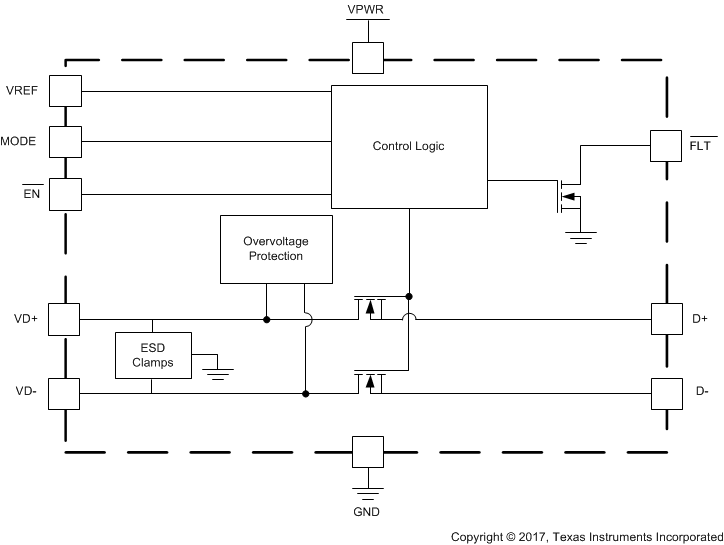
功能框图

TPD2S701-Q1 Function_Block.gif

4 修订历史

Changes from * Revision (April 2017) to A Revision

  • Updated Figure 19 Go

5 Pin Configuration and Functions

DGS Package
10-Pin SSOP
Top View
TPD2S701-Q1 DSG_sop_pin_diagram.gif
DSK Package
10-Pin QFN
Top View
TPD2S701-Q1 DSK_son_pin_diagram.gif

Pin Functions

PIN TYPE DESCRIPTION
NO. NAME
1 VD– I/O High voltage D– USB data line, connect to USB connector D+, D– IEC61000-4-2 ESD protection
2 VD+ I/O High voltage D+ USB data line, connect to USB connector D+, D– IEC61000-4-2 ESD protection
3 GND Ground Ground pin for internal circuits and IEC ESD clamps
4 FLT O Open-drain fault pin. See Table 1
5 EN I Enable active-low input. Drive EN low to enable the switches. Drive EN high to disable the switches. See Table 1 for mode selection
6 MODE I Selects between device modes. See the Detailed Description section. Acts as LDO reference voltage for mode 1
7 VPWR I 5-V DC supply input for internal circuits. Connect to internal power rail on PCB
8 VREF I/O Pin to set OVP threshold. See the Detailed Description section for instructions on how to set OVP threshold
9 D+ I/O I/O protected low voltage D+ USB data line, connects to transceiver
10 D– I/O Protected low voltage D– USB data line, connects to transceiver

6 Specifications

6.1 Absolute Maximum Ratings

over operating free-air temperature range (unless otherwise noted) (1) (2)
MIN MAX UNIT
VPWR 5-V DC supply voltage for internal circuitry –0.3 7.7
V
VREF Pin to set OVP threshold –0.3 6 V
VD+, VD– Voltage range from connector-side USB data lines –0.3 7.7 V
D+, D– Voltage range for internal USB data lines –0.3 VREF + 0.3 V
VMODE Voltage on MODE pin –0.3 7.7 V
VFLT Voltage on FLT pin –0.3 7.7 V
VEN Voltage on enable pin –0.3 7.7 V
TA Operating free air temperature(3) –40 125 °C
TSTG Storage temperature –65 150 °C
(1) Stresses beyond those listed under Absolute Maximum Ratings may cause permanent damage to the device. These are stress ratings only, which do not imply functional operation of the device at these or any other conditions beyond those indicated under Recommended Operating Conditions. Exposure to absolute-maximum-rated conditions for extended periods may affect device reliability.
(2) The algebraic convention, whereby the most negative value is a minimum and the most positive value is a maximum.
(3) Thermal limits and power dissipation limits must be observed.

6.2 ESD Ratings—AEC Specification

VALUE UNIT
V(ESD) Electrostatic discharge Human-body model (HBM), per AEC Q100-002(1) All pins ±2000 V
Charged-device model (CDM), per AEC Q100-011 All pins besides corners ±500
Corner pins ±750
(1) AEC Q100-002 indicates that HBM stressing shall be in accordance with the ANSI/ESDA/JEDEC JS-001 specification.

6.3 ESD Ratings—IEC Specification

VALUE UNIT
V(ESD) Electrostatic discharge IEC 61000-4-2 contact discharge VD+, VD– pins(1) ±8000 V
IEC 61000-4-2 air-gap discharge VD+, VD– pins(1) ±15000
(1) See Figure 19 for details on system level ESD testing setup.

6.4 ESD Ratings—ISO Specification

VALUE UNIT
VESD (1) Electrostatic discharge ISO 10605 (330 pF, 330 Ω) contact discharge (10 strikes) VD+, VD– pins ±8000 V
ISO 10605 (330 pF, 330 Ω) air-gap discharge (10 strikes) VD+, VD– pins ±15000
ISO 10605 (150 pF, 330 Ω) contact discharge (10 strikes) VD+, VD– pins ±8000
ISO 10605 (150 pF, 330 Ω) air-gap discharge (10 strikes) VD+, VD– pins ±15000
ISO 10605 (330 pF, 2 kΩ) contact discharge (10 stikes)(2) VD+, VD– pins ±8000
ISO 10605 (330 pF, 2 kΩ) air-gap discharge (10 strikes) VD+, VD– pins ±15000
ISO 10605 (150 pF, 2 kΩ) air-gap discharge (10 discharges) VD+, VD– pins ±25000
(1) See Figure 19 for details on system level ESD testing setup.
(2) VREF > 3 V.

6.5 Recommended Operating Conditions

over operating free-air temperature range (unless otherwise noted)
MIN TYP MAX UNIT
VPWR 5-V DC supply voltage for internal circuitry 4.5 7 V
VREF Mode 0. Voltage range for VREF pin (for setting OVP threshold) 3 3.6 V
VREF Mode 1. Voltage range for VREF pin (for setting OVP threshold) 0.63 3.8 V
VD+, VD– Voltage range from connector-side USB data lines 0 3.6 V
D+, D– Voltage range for internal USB data lines 0 3.6 V
VEN Voltage range for enable 0 7 V
VFLT Voltage range for FLT 0 7 V
IFLT Current into open drain FLT pin FET 0 3 mA
CVPWR VPWR capacitance(1) External Capacitor on VPWR pin 1 10 µF
CVREF VREF capacitance External Capacitor on VREF pin 0.3 1 3 µF
CMODE Allowed parasitic capacitance on mode pin from PCB and mode 1 external resistors 20 pF
RMODE_0 Resistance to GND to set to mode 0 2 2.6 kΩ
RMODE_1 Resistance to GND to set to mode 1 (calculate parallel combination of RTOP and RBOT) 14 20 kΩ
(1) For recommended values for capacitors and resistors, the typical values assume a component placed on the board near the pin. Minimum and maximum values listed are inclusive of manufacturing tolerances, voltage derating, board capacitance, and temperature variation. The effective value presented should be within the minimum and maximums listed in the table.

6.6 Thermal Information

THERMAL METRIC(1) TPD2S701-Q1 UNIT
DGS (VSSOP) DSK (WSON)
10 PINS 10 PINS
θJA Junction-to-ambient thermal resistance 167.3 61.5 °C/W
θJCtop Junction-to-case (top) thermal resistance 56.9 51.3 °C/W
θJB Junction-to-board thermal resistance 87.6 34 °C/W
ψJT Junction-to-top characterization parameter 7.7 1.3 °C/W
ψJB Junction-to-board characterization parameter 86.2 34.3 °C/W
θJCbot Junction-to-case (bottom) thermal resistance N/A 7.7 °C/W
(1) For more information about traditional and new thermal metrics, see the Semiconductor and IC Package Thermal Metrics application report.

6.7 Electrical Characteristics

over operating free-air temperature range (unless otherwise noted)
PARAMETER TEST CONDITIONS MIN TYP MAX UNIT
MODE 1 ADJUSTABLE VREF
VMODE_CMP Mode 1 VREF feedback regulator voltage VMODE Standard mode 1 set-up. EN = 0 V. Once VREF = 3.3 V, measure voltage on mode pin 0.47 0.5 0.53 V
IMODE_LEAK Mode pin mode 1 leakage current IMODE Standard mode 1. Remove RTOP and RBOT. Power up device and wait until start-up time has passed. Then force 0.53 V on the MODE pin and measure current into pin 50 200 nA
VREF_ACCURACY VREF accuracy VREF Informative, test parameters below; accuracy with RTOP and RBOT as ±1% resistors –8% 8%
VREF_3.3V Mode 1 VREF set to 3.3 V VREF Standard mode 1 set-up. RTOP = 140 kΩ ± 1%, RBOT = 24.9 kΩ ± 1%. EN = 0. Measure value of VREF once it settles 3.04 3.31 3.58 V
VREF_0.66V Mode 1 VREF set to 0.66 V VREF Standard mode 1 set-up. RTOP = 47.5 kΩ ± 1%, RBOT = 150 kΩ ± 1%.EN = 0. Measure value of VREF once it settles 0.6 0.66 0.72 V
VREF_3.8V Mode 1 VREF set to 3.8 V VREF Standard mode 1 set-up. RTOP = 165 kΩ ± 1%, RBOT = 24.9 kΩ ± 1%. EN = 0. Measure value of VREF once it settles 3.5 3.81 4.12 V
EN, FLT PINS
VIH High-level input voltage EN Mode 0. Connect VPWR = 5 V; VREF = 3.3 V; VD+ = 3.3 V; Set VIH(EN) = 0 V; Sweep VIH from 0 V to 1.4 V; Measure when D+ drops low (less than or equal to 5% of 3.3 V) from 3.3 V 1.2 V
Low-level input voltage Mode 0. Connect VPWR = 5 V; VREF = 3.3 V; VD+ = 3.3 V. Set VIH(EN) = 3.3 V; Sweep VIH from 3.3 V to 0.5 V; Measure when D+ rise to 95% of 3.3 V from 0 V 0.8
IIL Input leakage current EN Mode 0. VPWR = 5 V; VREF = 3.3 V; VI (EN) = 3.3 V ; Measure current into EN pin 1 µA
VOL Low-level output voltage FLT Mode 0. Drive the TPS2S701-Q1 in OVP to assert FLT pin. Source IOL = 1 mA into FLT pin and measure voltage on FLT pin when asserted 0.4 V
TSD_RISING The rising over temperature protection shutdown threshold VPWR = 5 V, ENZ = 0 V, TA stepped up until FLTZ is asserted 140 150 165 ℃
TSD_FALLING The falling over temperature protection shutdown threshold VPWR = 5 V, ENZ = 0 V, TA stepped down from TSD_RISING until FLTZ is cleared 125 138 150 ℃
TSD_HYST The over temperature protection shutdown threshold hysteresis TSD_RISING – TSD_FALLING 10 12 15 ℃
OVP CIRCUIT—VD±
VOVP_RISING Input overvoltage protection threshold, VREF > 3.6 V VD± Mode 1. Set VPWR = 5 V; EN = 0 V; RTOP = 165 kΩ, RBOT = 24.9 kΩ. Connect D± to 40-Ω load.  Increase VD+ or VD– from 4.1 V to 4.9 V. Measure the value at which FLTZ is asserted 4.3 4.5 4.7 V
VOVP_RISING Input overvoltage protection threshold VD± Mode 1. Set VPWR = 5 V; EN = 0 V; RTOP = 140 kΩ, RBOT = 24.9 kΩ. Increase VD+ or VD– from 3.6 V to 4.6 V. Measure the value at which FLTZ is asserted. Repeat for RTOP = 39 kΩ, RBOT = 150 kΩ. Increase VD+ or VD– from 0.6 V to 0.9 V. Measure the value at which FLTZ is asserted. See the resultant values meet the equation, and make sure to observe data switches turnoff.

Also check for mode 0 when VREF = 3.3 V
1.19 × VREF 1.25 × VREF 1.31 × VREF V
VHYS_OVP Hysteresis on OVP VD± Difference between rising and falling OVP thresholds on VD± 25 mV
VOVP_FALLING Input overvoltage protection threshold VD± After collecting each rising OVP threshold, lower the VD± voltage until you see FLT deassert. This gives the falling OVP threshold. Use this value to calculate VHYS_OVP VOVP_RISING – VHYS_OVP V
IVD_LEAK_0 V Leakage current on VD± during normal operation VD± Standard mode 0 or mode 1. Set VD± = 0 V. D± = floating. Measure current flowing into VD± –0.1 0.1 µA
IVD_LEAK_3.6V Leakage current on VD± during normal operation VD± Standard mode 0 or mode 1. Set VD± = 3.6 V. D± = floating. Measure current flowing into VD± 2.5 4 µA
VOVP_3.3V Input overvoltage threshold for VREF = 3.3 V VD± Standard mode 1. RTOP = 140 kΩ ± 1%, RBOT = 24.9 kΩ ± 1%. Connect D± to 40-Ω load.  Measure the value at which FLTZ is asserted 3.61 4.14 4.67 V
VOVP_0.66V Input overvoltage threshold for VREF = 0.66 V VD± Standard mode 1. RTOP = 47.5 kΩ ± 1%, RBOT = 150 kΩ ± 1%. Connect D± to 40-Ω load. Measure the value at which FLTZ is asserted 0.72 0.83 0.94 V
DATA LINE SWITCHES – VD+ to D+ or VD– to D–
RON On resistance Mode 0 or 1. Set VPWR = 5 V; VREF = 3.3 V; EN = 0 V; Measure resistance between D+ and VD+ or D– and VD–, voltage between 0 and 0.4 V 4 6.5 Ω
RON(Flat) On resistance flatness Mode 0 or 1. Set VPWR = 5 V; VREF = 3.3 V; EN = 0 V; Measure resistance between D+ and VD+ or D– and VD–, sweep voltage between 0 and 0.4 V. Take difference of resistance at 0.4-V and 0-V VD± bias 1 Ω
BWON On bandwidth (–3-dB) Mode 0 or 1. Set VPWR = 5 V; VREF = 3.3 V; EN = 0 V; Measure S21 bandwidth from D+ to VD+ or D– to VD– with voltage swing = 400 mVpp, Vcm = 0.2 V 960 MHz

6.8 Power Supply and Supply Current Consumption Chracteristics

over operating free-air temperature range (unless otherwise noted)
PARAMETER TEST CONDITIONS MIN TYP MAX UNIT
VUVLO_RISING_VPWR VPWR rising UVLO threshold Use standard mode 0 set-up. Set EN = 0 V, load D+ to 45 Ω, VD+ = 3.3 V. Set VPWR = 3.5 V, and step up VPWR until 90% of VD+ appears on D+ 3.7 3.95 4.2 V
VUVLO_HYST_VPWR VPWR UVLO hysteresis Use standard mode 0 set up. Set EN = 0 V, load D+ to 45 Ω, VD+ = 3.3 V. Set VPWR = 4.3 V, and step down VPWR until D+ falls to 10% of VD+. This gives VUVLO_FALLING_VPWR. VUVLO_RISING_VPWR – VUVLO_FALLING_VPWR = VUVLO_HYST_VPWR for this unit 250 300 400 mV
VUVLO_RISING_VREF VREF rising UVLO threshold in mode 0 Use standard mode 0 set up. Set EN = 0V, load D+ to 45 Ω, VD+ = 3.3 V. Set VREF = 2.5 V, and step up VREF until 90% of VD+ appears on D+ 2.6 2.7 2.9 V
VUVLO_HYST_VREF VREF UVLO hysteresis Use standard mode 0 set up. Set EN = 0 V, load D+ to 45 Ω, VD+ = 3.3 V. Set VREF = 3 V, and step down VREF until D+ falls to 10% of VD+. This gives VUVLO_FALLING_VREF. VUVLO_RISING_VREF –VUVLO_FALLING_VREF = VUVLO_HYST_VREF for this unit 75 125 200 mV
IVPWR_DISABLED_MODE0 VPWR disabled current consumption Use standard mode 0. EN = 5 V . Measure current into VPWR 110 µA
IVPWR_DISABLED_MODE1 VPWR disabled current consumption Use standard mode 1. EN = 5 V. Measure current into VPWR 110 µA
IVREF_DISABLED VREF disabled current consumption mode 0 Use standard mode 0. EN = 5 V. Measure current into VREF 10 µA
IVPWR_MODE0 VPWR pperating current consumption Use standard mode 0. EN = 0 V. Measure current into VPWR 250 µA
IVPWR_MODE1 VPWR operating current consumption Use standard mode 1. EN = 0 V. Measure current into VPWR 350 µA
IVREF VREF operating current consumption mode 0 Use standard mode 0. EN = 0 V. Measure current into VREF 12 20 µA
ICHG_VREF VREF fast charge current Standard mode 1. 0.1 µF < CVREF < 3 µF. Set-up for charging to 3.3 V. Use a high voltage capacitor that does not derate capacitance up the 3.3 V. Measure slope to calculate the current when CVREF cap is being charged. Test to check this OPEN LOOP method 22 mA
ID_OFF_LEAK_STB Mode 0. Measured flowing into D+ or D– supply, VPWR = 0 V, VD+ or VD– = 18 V, EN = 0 V, VREF = 0 V, D± = 0 V –1 1 µA
ID_ON_LEAK_STB Mode 0. Measured flowing into D+ or D– supply, VPWR = 5 V, VD+ or VD– = 18 V, EN = 0 V, VREF = 3.3 V, D± = 0 V –1 1 µA
IVD_OFF_LEAK_STB Mode 0. Measured flowing out of VD+ or VD– supply, VPWR = 0 V, VD+ or VD– = 18 V, EN = 0 V, VREF = 0 V, D± = 0 V 120
IVD_ON_LEAK_STB Mode 0. Measured flowing out of VD+ or VD– supply, VPWR = 5 V, VD+ or VD– = 18 V, EN = 0 V, VREF = 3.3 V, D± = 0 V 120 µA
IVPWR_TO_VREF_LEAK Leakage from VPWR to VREF Use standard mode 0.  Set VREF = 0 V.  Measured current flowing out of VREF pin 1 µA
IVREF_TO_VPWR_LEAK Leakage from VREF to VPWR Use standard mode 0.  Set VPWR = 0 V.  Measured as current flowing out of VPWR pin 1 µA

6.9 Timing Requirements

over operating free-air temperature range (unless otherwise noted)
MIN NOM MAX UNIT
ENABLE PIN AND VREF FAST CHARGE
TVREF_CHG VREF fast charge time Time between when 5 V is applied to VPWR, and VREF reaches VVREF_FAST_CHG. Needs to happen before or at same time tON_STARTUP completes 0.5 1 ms
TON_STARTUP_MODE0 Device turnon time from UVLO mode 0 Mode 0. EN = 0 V, measured from VPWR and VREF = UVLO+ to data FET ON, VPWR comes to UVLO+ second. Place 3.3 V on VD±. Ramp VREF to 3.3 V, then VPWR to 5 V and measure the time it takes for D± to reach 90% of VD± 0.5 1 ms
TON_STARTUP_MODE1 Device turnon time from UVLO mode 1 Informative. mode 1. EN = 0 V, measured from VPWR = UVLO+ to data FET ON 0.5 + TCHG_CVREF ms
TON_STARTUP_MODE1_3.3V Device turnon time from UVLO mode 1 Mode 1. EN = 0 V, measured from VPWR = UVLO+ to data FET ON, CVREF = 1 µF, VREF_FINAL = 3.3 V. Measure the time it takes for D± to reach 90% of VD± 0.6 1 ms
TON_EN_MODE0 Device turnon time mode 0 Mode 0. VPWR = 5 V, VREF = 3.3 V, time from EN is asserted until data FET is ON. Place 3.3 V on VD±, measure the time it takes for D± to reach 90% of VD± 150 µs
TON_EN_MODE1 Device turnon time mode 1 Mode 1. VPWR = 5 V, VREF_INITIAL = 0 V, time from EN is asserted until data FET is ON. Place 3.3 V on VD±, measure the time it takes for D± to reach 90% of VD± 150 + TCHG_VREF µs
TON_EN_MODE1_3.3V Device turnon time mode 1 for VREF = 3.3 V Mode 1. VPWR = 5 V, VREF_INITIAL = 0 V, time from EN is asserted until data FET is ON. Place 3.3 V on VD±, measure the time it takes for D± to reach 90% of VD±. CVREF = 1 µF, VREF_FINAL = 3.3 V 300 µs
TOFF_EN Device turnoff time Mode 0 or 1. VPWR = 5 V, VREF = 3.3 V, time from EN is deasserted until data FET is off. Place 3.3 V on VD±, measure the time it takes for D± to fall to 10% of VD±, RD± = 45 Ω 5 µs
TCHG_CVREF Time to charge CVREF Informative. Mode 1. Time from VREF = 0 V to 80% × VREF_FINAL after EN transitions from high to low (CVREF × 0.8 (VREF_FINAL)/(ICHG_VREF) s
TCHG_CVREF_3.3V Time to charge CVREF to 3.3 V Mode 1. Time from VREF = 0 V to 90% × 3.3 V after EN transitions from high to low, CVREF = 1 µF 132 µs
TCHG_CVREF_0.66V Time to charge CVREF to 0.66 V Mode 1. Time from VREF = 0 V to 90% × 0.63 V after EN transitions from high to low, CVREF = 1 µF. RTOP = 47.5 kΩ ± 1%, RBOT = 150 kΩ ± 1% 26 µs
OVERVOLTAGE PROTECTION
tOVP_response_VBUS OVP response time to VBUS Mode 0 or 1. Measured from OVP condition to FET turn off . Short VD± to 5 V and measure the time it takes D± voltage to reach 0.1 × VD±_CLAMP_MAX from the time the 5-V hot-plug is applied. RLOAD_D± = 45 Ω.(1) (2) 2 µs
tOVP_response OVP response time Mode 0 or 1. Measured from OVP condition to FET turn off . Short VD± to 18 V and measure the time it takes D± voltage to reach 0.1 × VD±_CLAMP_MAX from the time the 18-V hot-plug is applied. RLOAD_D± = 45 Ω(1) (2) 0.1 1 µs
tOVP_Recov _FLT Recovery time FLT pin Measured from OVP clear to FLT deassertion(1) 32 ms
tOVP_Recov _FET Recovery time for data FET to turn back on Measured from OVP clear until FET turns back on. Drop VD+ from 16 V to 3.3 V with VREF = 3.3 V, measure time it takes for D+ to reach 90% of 3.3 V 32 ms
tOVP_ASSERT FLT assertion time Measured from OVP on VD+ or VD– to FLT assertion 12.6 18 23.4 ms
(1) Shown in Figure 1.
(2) Specified by design, not production tested.
TPD2S701-Q1 OVP_Operation.gif
1. OVP Operation – VD+, VD–
Figure 1. TPD2S701-Q1 Timing Diagram

6.10 Typical Characteristics

TPD2S701-Q1 Fig1_SLLSEU8.gif
Figure 2. 8-kV IEC 61400-4-2 Contact Waveform
TPD2S701-Q1 Fig3_SLLSEU8.gif
Figure 4. 8-kV ISO 10605 (330-pF, 330-Ω) Contact Waveform
TPD2S701-Q1 Fig5_SLLSEU8.gif
Figure 6. Data Line I-V Curve
TPD2S701-Q1 Fig7_SLLSEU8.gif
Figure 8. VPWR Operating Current vs Bias Voltage
TPD2S701-Q1 D010_SLLSEU8.gif
Figure 10. VD± Leakage Current at 7 V Across Temperature (Enabled)
TPD2S701-Q1 D011_SLLSEU8.gif
Figure 12. Data Switch Short-to-5 V Response Waveform
TPD2S701-Q1 Fig14_SLLSEU8.gif
Figure 14. FLT Recover Time After OVP Clear
TPD2S701-Q1 D016_SLLSEU8.gif
Figure 16. Data Switch Single-Ended Bandwidth
TPD2S701-Q1 D019_SLLSEU8.gif
Figure 18. USB2.0 Eye Diagram (With TPD2S701-Q1)
TPD2S701-Q1 Fig2_SLLSEU8.gif
Figure 3. –8-kV IEC 61400-4-2 Contact Waveform
TPD2S701-Q1 Fig4_SLLSEU8.gif
Figure 5. –8-kV ISO 10605 (330-pF, 330-Ω) Contact Waveform
TPD2S701-Q1 Fig6_SLLSEU8.gif
Figure 7. Data Switch Turnon Time
TPD2S701-Q1 Fig8_SLLSEU8.gif
Figure 9. VPWR Operating Current vs Temperature
(VPWR = 5 V)
TPD2S701-Q1 Fig10_SLLSEU8.gif
Figure 11. Data Switch RON vs Bias Voltage
TPD2S701-Q1 Fig13_SLLSEU8.gif
Figure 13. FLT Assertion Time During OVP
TPD2S701-Q1 D015_SLLSEU8.gif
Figure 15. Data Switch Differential Bandwidth
TPD2S701-Q1 D018_SLLSEU8.gif
Figure 17. USB2.0 Eye Diagram (No TPD2S701-Q1)

7 Parameter Measurement Information

TPD2S701-Q1 sllsey0_esd_setup.gif Figure 19. ESD Setup

8 Detailed Description

8.1 Overview

The TPD2S701-Q1 is a 2-Channel Data Line Short-to-VBUS and IEC61000-4-2 ESD protection device for automotive high-speed interfaces like USB2.0. The TPD2S701-Q1 contains two data line nFET switches which ensure safe data communication while protecting the internal system circuits from any overvoltage conditions at the VD+ and VD– pins. On these pins, this device can handle overvoltage protection up to 7-V DC. This provides sufficient protection for shorting the data lines to the USB VBUS rail.

Additionally, the TPD2S701-Q1 has a FLT pin which provides an indication when the device sees an overvoltage condition and automatically resets when the overvoltage condition is removed. The TPD2S701-Q1 also integrates IEC ESD clamps on the VD+ and VD– pins, thus eliminating the need for external TVS clamp circuits in the application.

The TPD2S701-Q1 has an internal oscillator and charge pump that controls the turnon of the internal nFET switches. The internal oscillator controls the timers that enable the charge pump and resets the open-drain FLT output. If VD+ and VD– are less than VOVP, the internal charge pump is enabled. After an internal delay, the charge-pump starts-up, turning on the internal nFET switches. At any time, if VD+ or VD– rises above VOVP, TPD2S701-Q1 asserts FLT pin LOW and the nFET switches are turned off.

8.2 Functional Block Diagram

TPD2S701-Q1 Function_Block.gif

8.3 Feature Description

8.3.1 OVP Operation

When the VD+, or VD– voltages rise above VOVP, the internal nFET switches are turned off, protecting the transceiver from overvoltage conditions. The response is very rapid, with the FET switches turning off in less than 1 µs. Before the OVP condition, the FLT pin is High-Z, and is pulled HIGH via an external resistor to indicate there is no fault. Once the OVP condition occurs, the FLT pin is asserted LOW. When the VD+, or VD– voltages returns below VOVP – VHYS-OVP, the nFET switches are turned on again. When the OVP condition is cleared and the nFETs are completely turned on, the FLT is reset to high-Z.

8.3.2 OVP Threshold

TPD2S701-Q1 tpd2S-ovp-diagram.gif Figure 20. OVP Threshold

The OVP Threshold VOVP is set by VREF according to Equation 1, Equation 2 and Equation 3.

Equation 1. TPD2S701-Q1 OVP_Th_Equation_1.gif
Equation 2. TPD2S701-Q1 OVP_Th_Equation_2.gif
Equation 3. TPD2S701-Q1 OVP_Th_Equation_3.gif

Equation 1, Equation 2 and Equation 3 yield the typical VOVP values. See the parametric tables for the minimum and maximum values that include variation over temperature and process. Figure 20 gives a graphical representation of the relationship between VOVP and VREF.

VREF can be set either by an external regulator (Mode 0) or an internal adjustable regulator (Mode 1). See the VREF Operation section for more details on how to operate VREF in Mode 0 and Mode 1.

8.3.3 D± Clamping Voltage

The TPD2S701-Q1 provides a differentiated device architecture which allows the system designer to control the clamping voltage the protected transceiver sees from the D+ and D– pins. This architecture allows the system designer to minimize the amount of stress the transceiver sees during ESD events. The clamping voltage that appears on the D+ and D– lines during an ESD event obeys Equation 4.

Equation 4. TPD2S701-Q1 Equation_3.gif

Where VBR approximately = 0.7 V, IRDYN approximately = 1 V. By adjusting VREF, the clamping voltage of the D+ and D– lines can be adjusted. As VREF also controls the OVP threshold, take care to insure that the VREF setting both satisfies the OVP threshold requirements while simultaneously optimizing system protection on the D+ and D– lines.

The size of the capacitor used on the VREF pin also influences the clamping voltage as transient currents during ESD events flow into the VREF capacitor. This causes the VREF voltage to increase, and likewise the clamping voltage on D± according to Equation 4. The larger capacitor that is used, the better the clamping performance of the device is going to be. See the parametric tables for the clamping performance of the TPD2S701-Q1 with a 1-µF capacitor.

8.4 Device Functional Modes

The TPD2S701-Q1 has two modes of operation which vary the way the VREF pin functions. In Mode 0, the VREF pin is connected to an external regulator which sets the voltage on the VREF pin. In Mode 1, the TPD2S701-Q1 uses an adjustable internal regulator to set the VREF voltage. Mode 1 enables the system designer to operate the TPD2S701-Q1 with a single power supply, and have the flexibility to easily set the VREF voltage to any voltage between 0.6 V and 3.8 V with two external resistors.

9 Application and Implementation

NOTE

Information in the following applications sections is not part of the TI component specification, and TI does not warrant its accuracy or completeness. TI’s customers are responsible for determining suitability of components for their purposes. Customers should validate and test their design implementation to confirm system functionality.

9.1 Application Information

The TPD2S701-Q1 offers 2-channels of short-to-VBUS protection and IEC ESD protection for automotive high speed interfaces such as USB 2.0. For the overvoltage protection (OVP), this device integrates N-channel FET’s which quickly isolate (200 ns) the protected circuitry in the event of an overvoltage condition on the VD+ and VD– lines. With respect to the ESD protection, the TPD2S701-Q1 has an internal clamping diode on each data line (VD+ and VD–) which provides 8-kV contact ESD protection and 15-kV air-gap ESD protection. More details on the internal components of the TPD2S701-Q1 can be found in the Overview section.

The TPD2S701-Q1 also has the ability to vary the OVP threshold based on the configuration of the Mode pin and the voltage present on the VREF pin (0.6 V-4.5 V). This functionality is discussed in greater depth in the OVP Threshold section. Once the VREF threshold is crossed, a fault is detectable to the user through the FLT pin, where 5 V on the pin indicates no fault is detected, and 0 V-0.4 V represents a fault condition. Figure 21 shows the TPD2S701-Q1 in a typical application, interfacing between the protected internal circuitry and the connector side, where ESD vulnerability is at its highest.

9.2 Typical Application

TPD2S701-Q1 USB2_0_Port_Short_to_Battery_1_701.gif Figure 21. USB 2.0 Port With Short-to-VBUS and IEC ESD Protection

9.2.1 Design Requirements

9.2.1.1 Device Operation

Table 1 gives the complete device functionality in response to the EN pin, to overvoltage conditions at the connector (VD± pins), to thermal shutdown, and to the conditions of the VPWR, VREF, and MODE pins.

Table 1. Device Operation Table

Functional Mode EN MODE VREF VPWR VD± TJ FLT Comments
NORMAL OPERATION
Mode 0 unpowered 1 X Rbot ≤ 2.6 kΩ X X X X H Device unpowered, data switches open
Mode 0 unpowered 2 X Rbot ≤ 2.6 kΩ X X X X H Device unpowered, data switches open
Mode 1 unpowered X Rtop | | Rbot > 14 kΩ X X X X H Device unpowered, data switches open
Mode 0 disabled H Rbot ≤ 2.6 kΩ >UVLO >UVLO X <TSD H Device disabled, data switches open
Mode 1 disabled H Rtop | | Rbot > 14 kΩ Set by Rtop and Rbot >UVLO X <TSD H Device disabled, data switches open, VREF is disabled
Mode 0 enabled L Rbot ≤ 2.6 kΩ >UVLO >UVLO <OVP <TSD H Device enabled, data switches closed, VREF is the value set by the power supply on VREF
Mode 1 enabled L Rtop | | Rbot > 14 kΩ Set by Rtop and Rbot >UVLO <OVP <TSD H Device enabled, data switches closed, VREF is the value set by the Rtop and Rbot resistor divider
FAULT CONDITIONS
Mode 0 thermal shutdown X Rbot ≤ 2.6 kΩ X >UVLO X >TSD L Thermal shutdown, data switches opened, FLT pin asserted
Mode 1 thermal shutdown X Rtop | | Rbot > 14 kΩ Set by Rtop and Rbot >UVLO X >TSD L Thermal shutdown, data switches opened, VREF is disabled, FLT pin asserted
Mode 0 OVP fault L Rbot ≤ 2.6 kΩ >UVLO >UVLO >OVP <TSD L Data line overvoltage protection mode. OVP is set relative to the voltage on VREF. Data switches opened, FLT pin asserted
Mode 1 OVP fault L Rtop | | Rbot > 14 kΩ Set by Rtop and Rbot >UVLO >OVP <TSD L Data line overvoltage protection mode. OVP is set relative to the voltage on VREF. Data switches opened, fault pin asserted

9.2.2 Detailed Design Procedure

9.2.2.1 VREF Operation

The TPD2S701-Q1 has two modes of operation which vary the way the VREF pin functions. In Mode 0, the VREF pin is connected to an external regulator which sets the voltage on the VREF pin. In Mode 1, the TPD2S701-Q1 uses an adjustable internal regulator to set the VREF voltage. Mode 1 enables the system designer to operate the TPD2S701-Q1 with a single power supply, and have the flexibility to easily set the VREF voltage to any voltage between 0.6 V and 3.8 V with two external resistors.

9.2.2.1.1 Mode 0

To set the device into Mode 0, ensure that Rbot, resistance between the MODE pin and ground, is less than 2.6 kΩ. The easiest way to implement Mode 0 is to directly connect the mode pin to GND on your PCB. With this resistance condition met, connect VREF to an external regulator to set the VREF voltage.

9.2.2.1.2 Mode 1

To operate in Mode 1, ensure that Rtop || Rbot, resistance between the MODE pin and ground, is greater than 14 kΩ. This is accomplished by insuring Rtop || Rbot > 14 kΩ because when the device is initially powered up, VREF is at ground until the internal circuitry recognizes if the device is in Mode 1 or Mode 2.

In Mode 1, VREF is set by using an internal regulator to set the voltage. Using a resistor divider off of a feedback comparator is how to set VREF, similar to a standard LDO or DC/DC. VREF is set in Mode 1 according to Equation 5.

Equation 5. TPD2S701-Q1 Equation_1.gif

Equation 5 yields the typical value for VREF. When using ±1% resistors RTOP and RBOT, VREF accuracy is going to be ±5%. Therefore, the minimum and maximum values for VREF can be calculated off of the typical VREF. The parametric tables above give example RTOP and RBOT resistors to use for standard output VREF voltages for Mode 1.

9.2.2.2 Mode 1 Enable Timing

In Mode 1, when the TPD2S701-Q1 is disabled, the output regulator is disabled, leading VREF to discharge to 0 V through RTOP and RBOT. It is desired for VREF to be at 0 V when the device is disabled to minimize the clamping voltage during a power disabled ESD event. If VREF is at 0 V, this holds D± near ground during these fault events.

When enabling the TPD2S701-Q1, VREF is quickly charged up to insure a quick turnon time of the Data FETs. Data FET turnon is gated by VREF reaching 80% of its final voltage plus 150 µs to insure a proper OVP threshold is set before passing data. This prevents false OVPs due to normal operation. Because Data FET turnon is gated by charging the VREF clamping capacitor, the size of the capacitor influences the turnon time of the Data switches. The TPD2S701-Q1’s internal regulator uses a constant current source to quickly charge the VREF clamping capacitor, so the charging time of CVREF can easily be calculated with Equation 6.

Equation 6. TPD2S701-Q1 Equation_2.gif

Where CVREF is the clamping capacitance on VREF, VREFFINAL is the final value VREF is set to, and ICHG_VREF = 22 mA (typical). If VREF = 1 V, 0.8 is used in the above equation because 80% of VREF is the amount of time that gates the turnon of the Data FETs. Once tCHG_CVREF is calculated, the typical turnon time of the Data FETs can be calculated from Equation 7.

Equation 7. TPD2S701-Q1 Mode_Enable_Equation_4.gif

9.2.3 Application Curves

TPD2S701-Q1 D018_SLLSEU8.gif
Figure 22. USB2.0 Eye Diagram (Board Only, Through Path)
TPD2S701-Q1 D019_SLLSEU8.gif
Figure 23. USB2.0 Eye Diagram (System from Typical Application Schematic)

10 Power Supply Recommendations

10.1 VPWR Path

The VPWR pin provides power to the TPD2S701-Q1. A 10-μF capacitor is recommended on VPWR as close to the pin as possible for localized decoupling of transients. A supply voltage above the UVLO threshold for VPWR must be supplied for the device to power on.

10.2 VREF Pin

The VREF pin provides a voltage reference for the data switch OVP level as well as a bypass for ESD clamping. A 1-μF capacitor must be placed as close to the pin as possible and the supply must be set to be above the UVLO threshold for VREF.

11 Layout

11.1 Layout Guidelines

Proper routing and placement maintains signal integrity for high-speed signals. The following guidelines apply to the TPD2S701-Q1:

  • Place the bypass capacitors as close as possible to the VPWR and VREF pins. Capacitors must be attached to a solid ground. This minimizes voltage disturbances during transient events such as ESD or overcurrent conditions.
  • High speed traces (data switch path) must be routed as straight as possible and any sharp bends must be minimized.

Standard ESD recommendations apply to the VD+, VD- pins as well:

  • The optimum placement is as close to the connector as possible.
    • EMI during an ESD event can couple from the trace being struck to other nearby unprotected traces, resulting in early system failures.
    • The PCB designer must minimize the possibility of EMI coupling by keeping any unprotected traces away from the protected traces which are between the TVS and the connector.
  • Route the protected traces as straight as possible.
  • Eliminate any sharp corners on the protected traces between the TVS and the connector by using rounded corners with the largest radii possible.
    • Electric fields tend to build up on corners, increasing EMI coupling.

11.2 Layout Example

TPD2S701-Q1 TPD2S701_Q1_Layout.gif Figure 24. TPD2S701-Q1 Layout

12 器件和文档支持

12.1 文档支持

12.1.1 相关文档

请参阅如下相关文档:

《TPD2S701-Q1 评估模块用户指南》

12.2 接收文档更新通知

要接收文档更新通知,请导航至 TI.com 上的器件产品文件夹。请单击右上角的通知我 进行注册,即可收到任意产品信息更改每周摘要。有关更改的详细信息,请查看任意已修订文档中包含的修订历史记录。

12.3 社区资源

下列链接提供到 TI 社区资源的连接。链接的内容由各个分销商“按照原样”提供。这些内容并不构成 TI 技术规范,并且不一定反映 TI 的观点;请参阅 TI 的 《使用条款》。

    TI E2E™ 在线社区 TI 的工程师对工程师 (E2E) 社区。此社区的创建目的在于促进工程师之间的协作。在 e2e.ti.com 中,您可以咨询问题、分享知识、拓展思路并与同行工程师一道帮助解决问题。
    设计支持 TI 参考设计支持 可帮助您快速查找有帮助的 E2E 论坛、设计支持工具以及技术支持的联系信息。

12.4 商标

E2E is a trademark of Texas Instruments.

All other trademarks are the property of their respective owners.

12.5 静电放电警告

esds-image

ESD 可能会损坏该集成电路。德州仪器 (TI) 建议通过适当的预防措施处理所有集成电路。如果不遵守正确的处理措施和安装程序 , 可能会损坏集成电路。

ESD 的损坏小至导致微小的性能降级 , 大至整个器件故障。 精密的集成电路可能更容易受到损坏 , 这是因为非常细微的参数更改都可能会导致器件与其发布的规格不相符。

12.6 Glossary

SLYZ022 — TI Glossary.

This glossary lists and explains terms, acronyms, and definitions.

13 机械、封装和可订购信息

以下页面包括机械、封装和可订购信息。这些信息是指定器件的最新可用数据。这些数据发生变化时,我们可能不会另行通知或修订此文档。如欲获取此产品说明书的浏览器版本,请参见左侧的导航栏。


重要声明

德州仪器(TI) 及其下属子公司有权根据 JESD46 最新标准, 对所提供的产品和服务进行更正、修改、增强、改进或其它更改, 并有权根据 JESD48最新标准中止提供任何产品和服务。客户在下订单前应获取最新的相关信息, 并验证这些信息是否完整且是最新的。所有产品的销售都遵循在订单确认时所提供的TI 销售条款与条件。

TI 保证其所销售的组件的性能符合产品销售时 TI 半导体产品销售条件与条款的适用规范。仅在 TI 保证的范围内,且 TI 认为有必要时才会使用测试或其它质量控制技术。除非适用法律做出了硬性规定,否则没有必要对每种组件的所有参数进行测试。

TI 对应用帮助或客户产品设计不承担任何义务。客户应对其使用 TI 组件的产品和应用自行负责。为尽量减小与客户产品和应用相关的风险,客户应提供充分的设计与操作安全措施。

TI 不对任何 TI 专利权、版权、屏蔽作品权或其它与使用了 TI 组件或服务的组合设备、机器或流程相关的 TI 知识产权中授予 的直接或隐含权限作出任何保证或解释。TI所发布的与第三方产品或服务有关的信息,不能构成从 TI 获得使用这些产品或服 务的许可、授权、或认可。使用此类信息可能需要获得第三方的专利权或其它知识产权方面的许可,或是 TI 的专利权或其它知识产权方面的许可。

对于 TI 的产品手册或数据表中 TI 信息的重要部分,仅在没有对内容进行任何篡改且带有相关授权、条件、限制和声明的情况 下才允许进行复制。TI 对此类篡改过的文件不承担任何责任或义务。复制第三方的信息可能需要服从额外的限制条件。

在转售 TI 组件或服务时,如果对该组件或服务参数的陈述与 TI 标明的参数相比存在差异或虚假成分,则会失去相关 TI 组件或服务的所有明示或暗示授权,且这是不正当的、欺诈性商业行为。TI 对任何此类虚假陈述均不承担任何责任或义务。

客户认可并同意,尽管任何应用相关信息或支持仍可能由 TI 提供,但他们将独力负责满足与其产品及在其应用中使用 TI 产品相关的所有法律、法规和安全相关要求。客户声明并同意,他们具备制定与实施安全措施所需的全部专业技术和知识,可预见故障的危险后果、监测故障及其后果、降低有可能造成人身伤害的故障的发生机率并采取适当的补救措施。客户将全额赔偿因 在此类安全关键应用中使用任何 TI 组件而对 TI及其代理造成的任何损失。

在某些场合中,为了推进安全相关应用有可能对 TI 组件进行特别的促销。TI 的目标是利用此类组件帮助客户设计和创立其特有的可满足适用的功能安全性标准和要求的终端产品解决方案。尽管如此,此类组件仍然服从这些条款。

TI 组件未获得用于 FDA Class III(或类似的生命攸关医疗设备)的授权许可,除非各方授权官员已经达成了专门管控此类使 用的特别协议。

只有那些 TI 特别注明属于军用等级或“增强型塑料”的 TI 组件才是设计或专门用于军事/航空应用或环境的。购买者认可并同 意,对并非指定面向军事或航空航天用途的 TI组件进行军事或航空航天方面的应用,其风险由客户单独承担,并且由客户独 力负责满足与此类使用相关的所有法律和法规要求。

TI 已明确指定符合 ISO/TS16949 要求的产品,这些产品主要用于汽车。在任何情况下,因使用非指定产品而无法达到 ISO/TS16949要求,TI不承担任何责任。

产品

  • 数字音频: www.ti.com.cn/audio
  • 放大器和线性器件: www.ti.com.cn/amplifiers
  • 数据转换器: www.ti.com.cn/dataconverters
  • DLP® 产品: www.dlp.com
  • DSP - 数字信号处理器: www.ti.com.cn/dsp
  • 时钟和计时器: www.ti.com.cn/clockandtimers
  • 接口: www.ti.com.cn/interface
  • 逻辑: www.ti.com.cn/logic
  • 电源管理: www.ti.com.cn/power
  • 微控制器 (MCU): www.ti.com.cn/microcontrollers
  • RFID 系统: www.ti.com.cn/rfidsys
  • OMAP应用处理器: www.ti.com/omap
  • 无线连通性: www.ti.com.cn/wirelessconnectivity

应用

  • 通信与电信: www.ti.com.cn/telecom
  • 计算机及周边: www.ti.com.cn/computer
  • 消费电子: www.ti.com/consumer-apps
  • 能源: www.ti.com/energy
  • 工业应用: www.ti.com.cn/industrial
  • 医疗电子: www.ti.com.cn/medical
  • 安防应用: www.ti.com.cn/security
  • 汽车电子: www.ti.com.cn/automotive
  • 视频和影像: www.ti.com.cn/video

德州仪器在线技术支持社区: www.deyisupport.com

邮寄地址: 上海市浦东新区世纪大道1568 号,中建大厦32 楼邮政编码: 200122
Copyright© 2016, 德州仪器半导体技术(上海)有限公司


Texas Instruments

© Copyright 1995-2025 Texas Instruments Incorporated. All rights reserved.
Submit documentation feedback | IMPORTANT NOTICE | Trademarks | Privacy policy | Cookie policy | Terms of use | Terms of sale