• Menu
  • Product
  • Email
  • PDF
  • Order now
  • TPS22975 5.7V、6A、导通电阻为 16mΩ 的负载开关

    • ZHCSF80B May   2016  – September 2017 TPS22975

      PRODUCTION DATA.  

  • CONTENTS
  • SEARCH
  • TPS22975 5.7V、6A、导通电阻为 16mΩ 的负载开关
  1. 1 特性
  2. 2 应用
  3. 3 说明
  4. 4 修订历史记录
  5. 5 Device Comparison Table
  6. 6 Pin Configuration and Functions
  7. 7 Specifications
    1. 7.1 Absolute Maximum Ratings
    2. 7.2 ESD Ratings
    3. 7.3 Recommended Operating Conditions
    4. 7.4 Thermal Information
    5. 7.5 Electrical Characteristics—VBIAS = 5 V
    6. 7.6 Electrical Characteristics—VBIAS = 2.5 V
    7. 7.7 Switching Characteristics
    8. 7.8 Typical DC Characteristics
    9. 7.9 Typical AC Characteristics
  8. 8 Parameter Measurement Information
  9. 9 Detailed Description
    1. 9.1 Overview
    2. 9.2 Functional Block Diagram
    3. 9.3 Feature Description
      1. 9.3.1 Adjustable Rise Time
      2. 9.3.2 Quick-Output Discharge (QOD) (Optional)
      3. 9.3.3 Thermal Shutdown
    4. 9.4 Device Functional Modes
  10. 10Application and Implementation
    1. 10.1 Application Information
      1. 10.1.1 ON and OFF Control
      2. 10.1.2 Input Capacitor (CIN) (Optional)
      3. 10.1.3 Output Capacitor (CL) (Optional)
    2. 10.2 Typical Application
      1. 10.2.1 Design Requirements
      2. 10.2.2 Detailed Design Procedure
        1. 10.2.2.1 Inrush Current
      3. 10.2.3 Application Curves
  11. 11Power Supply Recommendations
  12. 12Layout
    1. 12.1 Layout Guidelines
    2. 12.2 Layout Example
    3. 12.3 Thermal Considerations
  13. 13器件和文档支持
    1. 13.1 器件支持
      1. 13.1.1 开发支持
    2. 13.2 相关文档
    3. 13.3 接收文档更新通知
    4. 13.4 社区资源
    5. 13.5 商标
    6. 13.6 静电放电警告
    7. 13.7 Glossary
  14. 14机械、封装和可订购信息
  15. 重要声明
search No matches found.
  • Full reading width
    • Full reading width
    • Comfortable reading width
    • Expanded reading width
  • Card for each section
  • Card with all content


DATA SHEET

TPS22975 5.7V、6A、导通电阻为 16mΩ 的负载开关

本资源的原文使用英文撰写。 为方便起见,TI 提供了译文;由于翻译过程中可能使用了自动化工具,TI 不保证译文的准确性。 为确认准确性,请务必访问 ti.com 参考最新的英文版本(控制文档)。

1 特性

  • 集成单通道负载开关
  • 输入电压范围:0.6V 至 VBIAS
  • VBIAS 电压范围:2.5V 至 5.7V
  • 导通电阻 (RON)
    • RON = 16m(VIN = 0.6V 到 5.7V,
      VBIAS = 5.7V 时的典型值)
  • 6A 最大持续开关电流
  • 低静态电流
    • 37µA(VIN = VBIAS = 5V 时的典型值)
  • 低控制输入阈值支持使用
    1.2V、1.8V、2.5V、3.3V 逻辑器件
  • 可配置的上升时间
  • 热关断
  • 快速输出放电 (QOD)(可选)
  • 带有散热焊盘的小外形尺寸无引线 (SON) 8 引脚封装
  • 经测试,静电放电 (ESD) 性能符合 JESD 22 规范
    • 2000V 人体模型 (HBM) 和 1000V 带电器件模型 (CDM)

2 应用

  • Ultrabook™
  • 笔记本电脑和上网本
  • 平板电脑
  • 消费类电子产品
  • 机顶盒和家庭网关
  • 电信系统
  • 固态硬盘 (SSD)

3 说明

TPS22975 产品系列包含两个器件:TPS22975 和 TPS22975N。每个器件都是一款单通道负载开关,可提供可配置的上升时间来尽量减小浪涌电流。此器件包括一个 N 通道金属氧化物半导体场效应晶体管 (MOSFET),可在 0.6 V 至 5.7V 的输入电压范围内运行并可支持 6A 的最大持续电流。此开关由一个开/关输入 (ON) 控制,此输入能够直接连接低电压控制信号。TPS22975 包含一个可选 230Ω 片上负载电阻,用于在此开关关断时进行快速输出放电。

TPS22975 采用小型,节省空间的 2mm × 2mm 8 引脚 SON 封装 (DSG),集成的散热焊盘允许该器件产生较高的功率耗散。该器件在自然通风环境下的额定运行温度范围为 –40°C 至 +105°C。

器件信息(1)

器件型号 封装 封装尺寸(标称值)
TPS22975
TPS22975N
WSON (8) 2.00mm x 2.00mm
  1. 要了解所有可用封装,请参阅数据表末尾的可订购产品附录。


简化电路原理图

TPS22975 application_circuit_02_SLVSDD0.gif

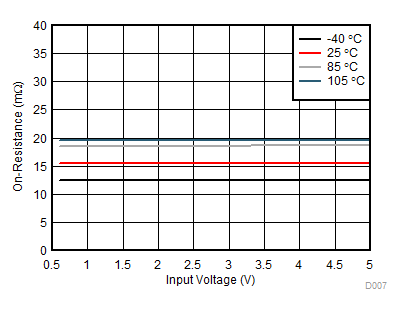
导通电阻与输入电压间的关系

TPS22975 D007_SLVSDD0A.gif
VBIAS = 5V,IVOUT = –200mA

4 修订历史记录

Changes from A Revision (June 2016) to B Revision

  • Updated VIH in Recommended Operating ConditionsGo

Changes from * Revision (May 2016) to A Revision

  • 器件状态,从产品预览改为量产数据Go

5 Device Comparison Table

DEVICE RON AT VIN = VBIAS = 5 V (TYPICAL) QUICK-OUTPUT DISCHARGE MAXIMUM OUTPUT CURRENT ENABLE
TPS22975 16 mΩ Yes 6 A Active high
TPS22975N 16 mΩ No 6 A Active high

6 Pin Configuration and Functions

DSG Package
8-Pin (WSON)
Top View
TPS22975 pinout_top_slvsdd0.gif
DSG Package
8-Pin (WSON)
Bottom View
TPS22975 pinout_bottom_slvsdd0.gif

Pin Functions

PIN I/O DESCRIPTION
NO. NAME
1 VIN I Switch input. Input bypass capacitor recommended for minimizing VIN dip. Must be connected to Pin 1 and Pin 2. See the Application and Implementation section for more information
2
3 ON I Active high switch control input. Do not leave floating
4 VBIAS I Bias voltage. Power supply to the device. Recommended voltage range for this pin is 2.5 V to 5.7 V. See the Application and Implementation section for more information
5 GND — Device ground
6 CT O Switch slew rate control. Can be left floating. See the Adjustable Rise Time section under Feature Description for more information
7 VOUT O Switch output
8
— Thermal Pad — Thermal pad (exposed center pad) to alleviate thermal stress. Tie to GND. See the Layout Example section for layout guidelines

7 Specifications

7.1 Absolute Maximum Ratings

Over operating free-air temperature range (unless otherwise noted)(1)
MIN MAX UNIT
VIN Input voltage –0.3 6 V
VOUT Output voltage –0.3 6 V
VBIAS Bias voltage –0.3 6 V
VON On voltage –0.3 6 V
IMAX Maximum continuous switch current 6 A
IPLS Maximum pulsed switch current, pulse < 300 µs, 2% duty cycle 8 A
TJ Maximum junction temperature 125 °C
Tstg Storage temperature –65 150 °C
(1) Stresses beyond those listed under Absolute Maximum Ratings may cause permanent damage to the device. These are stress ratings only, which do not imply functional operation of the device at these or any other conditions beyond those indicated under Recommended Operating Conditions. Exposure to absolute-maximum-rated conditions for extended periods may affect device reliability.

7.2 ESD Ratings

VALUE UNIT
V(ESD) Electrostatic discharge Human-body model (HBM), per ANSI/ESDA/JEDEC JS-001(1) ±2000 V
Charged-device model (CDM), per JEDEC specification JESD22-C101(2) ±1000
(1) JEDEC document JEP155 states that 500-V HBM allows safe manufacturing with a standard ESD control process.
(2) JEDEC document JEP157 states that 250-V CDM allows safe manufacturing with a standard ESD control process.

7.3 Recommended Operating Conditions

MIN MAX UNIT
VIN Input voltage 0.6 VBIAS V
VBIAS Bias voltage 2.5 5.7 V
VON ON voltage 0 5.7 V
VOUT Output voltage VIN V
VIH High-level input voltage, ON VBIAS = 2.5 V to 5 V, TA< 85°C 1.05 5.7 V
VBIAS = 2.5 V to 5 V, TA< 105°C 1.1 5.7
VBIAS = 5 V to 5.7 V, TA< 105°C 1.2 5.7
VIL Low-level input voltage, ON VBIAS = 2.5 V to 5.7 V 0 0.5 V
CIN Input capacitor 1(1) µF
TA Operating free-air temperature(1)(2) –40 105 °C
(1) See the Application Information section.
(2) In applications where high power dissipation and-or poor package thermal resistance is present, the maximum ambient temperature may have to be derated and device lifetime may be affected. Maximum ambient temperature (TA(max)) is dependent on the maximum operating junction temperature (TJ(max)), the maximum power dissipation of the device in the application (PD(max)), and the junction-to-ambient thermal resistance of the part-package in the application (θJA), and can be approximated by the following equation: TA (max) = TJ(max) – (θJA × PD(max)).

7.4 Thermal Information

THERMAL METRIC(1) TPS22975 UNIT
DSG (WSON)
8 PINS
RθJA Junction-to-ambient thermal resistance 74.8 °C/W
RθJC(top) Junction-to-case (top) thermal resistance 81 °C/W
RθJB Junction-to-board thermal resistance 44.7 °C/W
ψJT Junction-to-top characterization parameter 3.9 °C/W
ψJB Junction-to-board characterization parameter 45.1 °C/W
RθJC(bot) Junction-to-case (bottom) thermal resistance 16.4 °C/W
(1) For more information about traditional and new thermal metrics, see the Semiconductor and IC Package Thermal Metrics application report.

7.5 Electrical Characteristics—VBIAS = 5 V

Unless otherwise noted, the specifications in the following table applies where VBIAS = 5 V. Typical values are for TA = 25 °C.
PARAMETER TEST CONDITIONS TA MIN TYP MAX UNIT
POWER SUPPLIES AND CURRENTS
IQ, VBIAS VBIAS quiescent current IOUT = 0 A,
VIN = VON = 5 V
–40°C to +105°C 37 45 µA
ISD, VBIAS VBIAS shutdown current VON = VOUT = 0 V –40°C to +105°C 2.3 µA
ISD, VIN VIN off-state supply current VON = VOUT = 0 V VIN = 5 V –40°C to +85°C 0.005 5 µA
–40°C to +105°C 10
VIN = 3.3 V –40°C to +85°C 0.002 1.5
–40°C to +105°C 3.5
VIN = 1.8 V –40°C to +85°C 0.002 1
–40°C to +105°C 2
VIN = 0.6 V –40°C to +85°C 0.001 0.5
–40°C to +105°C 1
ION On-pin input leakage current VON = 5.5 V –40°C to +105°C 0.1 µA
RESISTANCE CHARACTERISTICS
RON On-resistance IOUT = –200 mA VIN = 5 V 25°C 16 19 mΩ
–40°C to +85°C 23
–40°C to +105°C 25
VIN = 3.3 V 25°C 16 19
–40°C to +85°C 23
–40°C to +105°C 25
VIN = 1.8 V 25°C 16 19
–40°C to +85°C 23
–40°C to +105°C 25
VIN = 1.5 V 25°C 16 19
–40°C to +85°C 23
–40°C to +105°C 25
VIN = 1.05 V 25°C 16 19
–40°C to +85°C 23
–40°C to +105°C 25
VIN = 0.6 V 25°C 16 19
–40°C to +85°C 23
–40°C to +105°C 25
VON, HYS On-pin hysteresis VIN = 5 V 25°C 120 mV
RPD (1) Output pulldown resistance VIN = 5 V, VON = 0 V –40°C to +105°C 230 300 Ω
TSD Thermal shutdown Junction temperature rising 160 °C
TSD, HYS Thermal shutdown hysteresis Junction temperature falling 20 °C
(1) TPS22975 only

7.6 Electrical Characteristics—VBIAS = 2.5 V

Unless otherwise noted, the specifications in the following table applies where VBIAS = 2.5 V. Typical values are for TA = 25 °C.
PARAMETER TEST CONDITIONS TA MIN TYP MAX UNIT
POWER SUPPLIES AND CURRENTS
IQ, VBIAS VBIAS quiescent current IOUT = 0 mA,
VIN = VON = 2.5 V
–40°C to +105°C 14 20 µA
ISD, VBIAS VBIAS shutdown current VON = VOUT = 0 V –40°C to +105°C 1 µA
ISD, VIN VIN off-state supply current VON = VOUT = 0 V VIN = 2.5 V –40°C to +85°C 0.005 1.3 µA
–40°C to +105°C 2.6
VIN = 1.8 V –40°C to +85°C 0.002 1
–40°C to +105°C 2
VIN = 1.05 V –40°C to +85°C 0.002 0.8
–40°C to +105°C 1.5
VIN = 0.6 V –40°C to +85°C 0.001 0.5
–40°C to +105°C 1
ION On-pin input leakage current VON = 5.5 V –40°C to +105°C 0.1 µA
RESISTANCE CHARACTERISTICS
RON On-resistance IOUT = –200 mA VIN = 2.5 V 25°C 20 26 mΩ
–40°C to +85°C 32
–40°C to +105°C 34
VIN = 1.8 V 25°C 18 23
–40°C to +85°C 29
–40°C to +105°C 31
VIN = 1.5 V 25°C 18 22
–40°C to +85°C 28
–40°C to +105°C 30
VIN = 1.2 V 25°C 17 22
–40°C to +85°C 27
–40°C to +105°C 29
VIN = 0.6 V 25°C 17 21
–40°C to +85°C 26
–40°C to +105°C 27
VON, HYS On-pin hysteresis VIN = 2.5 V 25°C 85 mV
RPD(1) Output pulldown resistance VIN = 2.5 V, VON = 0 V –40°C to +105°C 230 330 Ω
TSD Thermal shutdown Junction temperature rising 160 °C
TSD, HYS Thermal shutdown hysteresis Junction temperature falling 20 °C
(1) TPS22975 only

7.7 Switching Characteristics

PARAMETER TEST CONDITION MIN TYP MAX UNIT
VIN = VBIAS = 5 V, TA = 25ºC (unless otherwise noted)
tON Turnon time RL = 10 Ω, CL = 0.1 µF, CIN = 1 µF, CT = 1000 pF, VON = 5 V 1450 µs
tOFF Turnoff time RL = 10 Ω, CL = 0.1 µF, CIN = 1 µF, CT = 1000 pF, VON = 5 V 2
tR VOUT rise time RL = 10 Ω, CL = 0.1 µF, CIN = 1 µF, CT = 1000 pF, VON = 5 V 1750
tF VOUT fall time RL = 10 Ω, CL = 0.1 µF, CIN = 1 µF, CT = 1000 pF, VON = 5 V 2
tD ON delay time RL = 10 Ω, CL = 0.1 µF, CIN = 1 µF, CT = 1000 pF, VON = 5 V 600
VIN = 0.6 V, VBIAS = 5 V, TA = 25ºC (unless otherwise noted)
tON Turnon time RL = 10 Ω, CL = 0.1 µF, CIN = 1 µF, CT = 1000 pF, VON = 5 V 620 µs
tOFF Turnoff time RL = 10 Ω, CL = 0.1 µF, CIN = 1 µF, CT = 1000 pF, VON = 5 V 2
tR VOUT rise time RL = 10 Ω, CL = 0.1 µF, CIN = 1 µF, CT = 1000 pF, VON = 5 V 280
tF VOUT fall time RL = 10 Ω, CL = 0.1 µF, CIN = 1 µF, CT = 1000 pF, VON = 5 V 2
tD ON delay time RL = 10 Ω, CL = 0.1 µF, CIN = 1 µF, CT = 1000 pF, VON = 5 V 485
VIN = VBIAS = 2.5 V, TA = 25ºC (unless otherwise noted)
tON Turnon time RL = 10 Ω, CL = 0.1 µF, CIN = 1 µF, CT = 1000 pF, VON = 5 V 2180 µs
tOFF Turnoff time RL = 10 Ω, CL = 0.1 µF, CIN = 1 µF, CT = 1000 pF, VON = 5 V 2
tR VOUT rise time RL = 10 Ω, CL = 0.1 µF, CIN = 1 µF, CT = 1000 pF, VON = 5 V 2150
tF VOUT fall time RL = 10 Ω, CL = 0.1 µF, CIN = 1 µF, CT = 1000 pF, VON = 5 V 2
tD ON delay time RL = 10 Ω, CL = 0.1 µF, CIN = 1 µF, CT = 1000 pF, VON = 5 V 1120
VIN = 0.6 V, VBIAS = 2.5 V, TA = 25ºC (unless otherwise noted)
tON Turnon time RL = 10 Ω, CL = 0.1 µF, CIN = 1 µF, CT = 1000 pF, VON = 5 V 1315 µs
tOFF Turnoff time RL = 10 Ω, CL = 0.1 µF, CIN = 1 µF, CT = 1000 pF, VON = 5 V 3
tR VOUT rise time RL = 10 Ω, CL = 0.1 µF, CIN = 1 µF, CT = 1000 pF, VON = 5 V 650
tF VOUT fall time RL = 10 Ω, CL = 0.1 µF, CIN = 1 µF, CT = 1000 pF, VON = 5 V 2
tD ON delay time RL = 10 Ω, CL = 0.1 µF, CIN = 1 µF, CT = 1000 pF, VON = 5 V 975

7.8 Typical DC Characteristics

TPS22975 D001_SLVSDD0A.gif
VIN = VBIAS VON = 5 V VOUT = 0 V
Figure 1. VBIAS Quiescent Current vs Bias Voltage
TPS22975 D003_SLVSDD0A.gif
VIN = VBIAS VON = 0 V VOUT = 0 V
Figure 3. VBIAS Shutdown Current vs Bias Voltage
TPS22975 D005_SLVSDD0A.gif
VBIAS = 5 V IOUT = –200 mA VON = 5 V
Note: All three RON curves have the same values; therefore, only one line is visible.
Figure 5. On-Resistance vs Ambient Temperature
TPS22975 D007_SLVSDD0A.gif
VBIAS = 5 V IOUT = –200 mA VON = 5 V
Figure 7. On-Resistance vs Input Voltage
TPS22975 D009_SLVSDD0A.gif
TA = 25°C IOUT = –200 mA VON = 5 V
Figure 9. On-Resistance vs Bias Voltage
TPS22975 D002_SLVSDD0A.gif
VBIAS = 5 V VON = 5 V VOUT = 0 V
Figure 2. VBIAS Quiescent Current vs Input Voltage
TPS22975 D004_SLVSDD0A.gif
VBIAS = 5 V VON = 0 V VOUT = 0 V
Figure 4. VIN Off-State Supply Current vs Input Voltage
TPS22975 D006_SLVSDD0A.gif
VBIAS = 2.5 V IOUT = –200 mA VON = 5 V
Figure 6. On-Resistance vs Ambient Temperature
TPS22975 D008_SLVSDD0A.gif
VBIAS = 2.5 V IOUT = –200 mA VON = 5 V
Figure 8. On-Resistance vs Input Voltage
TPS22975 D010_SLVSDD0A.gif
VIN = 2.5 V VON = 0 V
Figure 10. Output Pull Down Resistance vs Bias Voltage

7.9 Typical AC Characteristics

TA = 25°C, CT = 1000 pF, CIN = 1 µF, CL = 0.1 µF, RL = 10 Ω
TPS22975 D011_SLVSDD0A.gif
VBIAS = 2.5 V
Figure 11. Delay Time vs Input Voltage
TPS22975 D013_SLVSDD0A.gif
VBIAS = 2.5 V
Figure 13. Fall Time vs Input Voltage
TPS22975 D015_SLVSDD0A.gif
VBIAS = 2.5 V
Figure 15. Turnoff Time vs Input Voltage
TPS22975 D017_SLVSDD0A.gif
VBIAS = 2.5 V
Figure 17. Turnon Time vs Input Voltage
TPS22975 D019_SLVSDD0A.gif
VBIAS = 2.5 V
Figure 19. Rise Time vs Input Voltage
TPS22975 SC_003.gif
VIN = 0.6 V VBIAS = 2.5 V
Figure 21. Turnon Response Time
TPS22975 SC_004.gif
VIN = 2.5 V VBIAS = 2.5 V
Figure 23. Turnon Response Time
TPS22975 SC_007.gif
VIN = 0.6 V VBIAS = 2.5 V
Figure 25. Turnoff Response Time
TPS22975 SC_008.gif
VIN = 2.5 V VBIAS = 2.5 V
Figure 27. Turnoff Response Time
TPS22975 D012_SLVSDD0A.gif
VBIAS = 5 V
Figure 12. Delay Time vs Input Voltage
TPS22975 D014_SLVSDD0A.gif
VBIAS = 5 V
Figure 14. Fall Time vs Input Voltage
TPS22975 D016_SLVSDD0A.gif
VBIAS = 5 V
Figure 16. Turnoff Time vs Input Voltage
TPS22975 D018_SLVSDD0A.gif
VBIAS = 5 V
Figure 18. Turnon Time vs Input Voltage
TPS22975 D020_SLVSDD0A.gif
VBIAS = 5 V
Figure 20. Rise Time vs Input Voltage
TPS22975 SC_001.gif
VIN = 0.6 V VBIAS = 5 V
Figure 22. Turnon Response Time
TPS22975 SC_002.gif
VIN = 5 V VBIAS = 5 V
Figure 24. Turnon Response Time
TPS22975 SC_005.gif
VIN = 0.6 V VBIAS = 5 V
Figure 26. Turnoff Response Time
TPS22975 SC_006.gif
VIN = 5 V VBIAS = 5 V
Figure 28. Turnoff Response Time

8 Parameter Measurement Information

TPS22975 application_circuit_02_SLVSDD0.gif
A. Rise and fall times of the control signal are 100 ns.
B. Turnoff times and fall times are dependent on the time constant at the load. For the TPS22975, the internal pull-down resistance RPD is enabled when the switch is disabled. The time constant is (RPD || RL) × CL.
Figure 29. Test Circuit
TPS22975 time_wave_slvsco0.gif Figure 30. tON and tOFF Waveforms

9 Detailed Description

9.1 Overview

The TPS22975 device is a single-channel, 6-A load switch in an 8-pin SON package. To reduce the voltage drop in high current rails, the device implements an N-channel MOSFET. The device has a configurable slew rate for applications that require a specific rise-time.

The device prevents downstream circuits from pulling high standby current from the supply by limiting the leakage current of the device when it is disabled. The integrated control logic, driver, power supply, and output discharge FET eliminates the need for any external components, which reduces solution size and bill of materials (BOM) count.

9.2 Functional Block Diagram

TPS22975 fbd_02_SLVSDD0.gif

9.3 Feature Description

9.3.1 Adjustable Rise Time

A capacitor to GND on the CT pin sets the slew rate. The voltage on the CT pin can be as high as 15 V; therefore, the minimum voltage rating for the CT capacitor must be 30 V for optimal performance. An approximate formula for the relationship between CT and slew rate when VBIAS is set to 5 V is shown in Equation 1. This equation accounts for 10% to 90% measurement on VOUT and does not apply for CT < 100 pF. Use Table 1 to determine rise times for when CT = 0 pF.

Equation 1. TPS22975 Equation1_SLVSDD0.gif

where

  • SR is the slew rate (in µs/V)
  • CT is the capacitance value on the CT pin (in pF)
  • The units for the constant 26 are µs/V. The units for the constant 0.43 are µs/(V × pF).

Rise time can be calculated by multiplying the input voltage by the slew rate. Table 1 contains rise time values measured on a typical device. Rise times shown in Table 1 are only valid for the power-up sequence where VIN and VBIAS are already in steady state condition before the ON pin is asserted high.

Table 1. Rise Time tR vs CT Capacitor

CT (pF) RISE TIME (µs) 10% - 90%, CL = 0.1 µF, CIN = 1 µF, RL = 10 Ω, VBIAS = 5 V(1)
VIN = 5 V VIN = 3.3 V VIN = 1.8 V VIN = 1.5 V VIN = 1.2 V VIN = 1.05 V VIN = 0.6 V
0 140 105 75 65 60 55 40
220 520 360 215 185 160 140 95
470 970 660 385 330 275 240 155
1000 1750 1190 700 595 495 435 275
2200 3875 2615 1520 1290 1070 940 595
4700 7580 5110 2950 2510 2075 1830 1150
10000 16980 11485 6650 5635 4685 4110 2595
(1) Typical Values at 25°C with a 25-V X7R 10% Ceramic Capacitor on CT

9.3.2 Quick-Output Discharge (QOD) (Optional)

The TPS22975 includes an optional QOD feature. When the switch is disabled, an internal discharge resistance is connected between VOUT and GND to remove the remaining charge from the output. This resistance has a typical value of 230 Ω and prevents the output from floating while the switch is disabled. For best results, it is recommended that the device gets disabled before VBIAS falls below the minimum recommended voltage.

9.3.3 Thermal Shutdown

Thermal shutdown protects the part from internally or externally generated excessive temperatures. When the device temperature triggers TSD (typical 160°C), the switch is turned off. The switch automatically turns on again if the temperature of the die drops 20 degrees below the TSD threshold.

9.4 Device Functional Modes

The Table 2 lists the VOUT pin states as determined by the ON pin.

Table 2. VOUT Connection

ON TPS22975 TPS22975N
L GND Open
H VIN VIN

10 Application and Implementation

NOTE

Information in the following applications sections is not part of the TI component specification, and TI does not warrant its accuracy or completeness. TI’s customers are responsible for determining suitability of components for their purposes. Customers should validate and test their design implementation to confirm system functionality.

10.1 Application Information

10.1.1 ON and OFF Control

The ON pin controls the state of the switch. ON is active high and has a 1.2-V ON-pin enable threshold, making it capable of interfacing with low-voltage signals. The ON pin is compatible with standard GPIO logic thresholds. It can be used with any microcontroller with 1.2 V or higher GPIO voltage. This pin cannot be left floating and must be driven either high or low for proper functionality.

10.1.2 Input Capacitor (CIN) (Optional)

To limit the voltage drop on the input supply caused by transient inrush currents when the switch turns on into a discharged load capacitor or short-circuit, a capacitor needs to be placed between VIN and GND. A 1-µF ceramic capacitor, CIN, placed close to the pins, is usually sufficient. Higher values of CIN can be used to further reduce the voltage drop during high current applications. When switching heavy loads, it is recommended to have an input capacitor about 10 times higher than the output capacitor (CL) to avoid excessive voltage drop.

10.1.3 Output Capacitor (CL) (Optional)

Because of the integrated body diode in the NMOS switch, a CIN greater than CL is highly recommended. A CL greater than CIN can cause VOUT to exceed VIN when the system supply is removed. This could result in current flow through the body diode from VOUT to VIN. A CIN to CL ratio of 10 to 1 is recommended for minimizing VIN dip caused by inrush currents during startup; however, a 10 to 1 ratio for capacitance is not required for proper functionality of the device. A ratio smaller than 10 to 1 (such as 1 to 1) could cause slightly more VIN dip upon turn-on because of inrush currents. This can be mitigated by increasing the capacitance on the CT pin for a longer rise time (see the Adjustable Rise Time section).

10.2 Typical Application

For optimal RON performance, it is recommended to have VIN ≤ VBIAS. The device is functional if VIN > VBIAS but it exhibits RON greater than what is listed in the Electrical Characteristics—VBIAS = 5 V and Electrical Characteristics—VBIAS = 2.5 V tables.

Figure 31 demonstrates how the TPS22975 can be used to power downstream modules.

TPS22975 application_circuit_02_SLVSDD0.gif Figure 31. Powering a Downstream Module

10.2.1 Design Requirements

DESIGN PARAMETER EXAMPLE VALUE
VIN 3.3 V
VBIAS 5 V
CL 22 µF
Maximum Acceptable Inrush Current 400 mA

10.2.2 Detailed Design Procedure

10.2.2.1 Inrush Current

When the switch is enabled, the output capacitors must be charged up from 0 V to the set value (3.3 V in this example). This charge arrives in the form of inrush current. Inrush current can be calculated using Equation 2.

Equation 2. Inrush Current = CL × dVOUT/dt

where

  • CL is the output capacitance
  • dVOUT is the change in VOUT during the ramp up of the output voltage when device is enabled.
  • dt is the rise time in VOUT during the ramp up of the output voltage when the device is enabled.

The TPS22975 offers adjustable rise time for VOUT. This feature allows the user to control the inrush current during turnon. The appropriate rise time can be calculated using the design requirements and the inrush current equation as shown in Equation 3.

Equation 3. 400 mA = 22 µF × 3.3 V/dt

The value of dt is given by Equation 4.

Equation 4. dt = 181.5 µs

To ensure an inrush current of less than 400 mA, choose a CT value that yields a rise time of more than 181.5 µs. See the oscilloscope captures in the Application Curves section for an example of how the CT capacitor can be used to reduce inrush current.

10.2.3 Application Curves

TPS22975 SC_009_2.png
VBIAS = 5 V VIN = 3.3 V CL = 22 µF
Figure 32. Inrush Current with CT = 0 pF
TPS22975 SC_010_2.png
VBIAS = 5 V VIN = 3.3 V CL = 22 µF
Figure 33. Inrush Current with CT = 220 pF


Texas Instruments

© Copyright 1995-2025 Texas Instruments Incorporated. All rights reserved.
Submit documentation feedback | IMPORTANT NOTICE | Trademarks | Privacy policy | Cookie policy | Terms of use | Terms of sale