• Menu
  • Product
  • Email
  • PDF
  • Order now
  • TPS63024x 高电流、高效单电感器降压-升压转换器

    • ZHCSDM2A November   2014  – December 2014 TPS63024 , TPS630241 , TPS630242

      PRODUCTION DATA.  

  • CONTENTS
  • SEARCH
  • TPS63024x 高电流、高效单电感器降压-升压转换器
  1. 1 特性
  2. 2 应用范围
  3. 3 说明
  4. 4 修订历史记录
  5. 5 Pin Configuration and Functions
  6. 6 Specifications
    1. 6.1 Absolute Maximum Ratings
    2. 6.2 ESD Ratings
    3. 6.3 Recommended Operating Conditions
    4. 6.4 Thermal Information
    5. 6.5 Electrical Characteristics
    6. 6.6 Timing Requirements
    7. 6.7 Typical Characteristics
  7. 7 Detailed Description
    1. 7.1 Overview
    2. 7.2 Functional Block Diagram
    3. 7.3 Feature Description
      1. 7.3.1 Undervoltage Lockout (UVLO)
      2. 7.3.2 Output Discharge Function
      3. 7.3.3 Thermal Shutdown
      4. 7.3.4 Softstart
      5. 7.3.5 Short Circuit Protection
    4. 7.4 Device Functional Modes
      1. 7.4.1 Control Loop Description
      2. 7.4.2 Power Save Mode Operation
      3. 7.4.3 Current Limit
      4. 7.4.4 Supply and Ground
      5. 7.4.5 Device Enable
  8. 8 Application and Implementation
    1. 8.1 Application Information
    2. 8.2 Typical Application
      1. 8.2.1 Design Requirements
      2. 8.2.2 Detailed Design Procedure
        1. 8.2.2.1 Output Filter Design
        2. 8.2.2.2 Inductor Selection
        3. 8.2.2.3 Capacitor Selection
          1. 8.2.2.3.1 Input Capacitor
          2. 8.2.2.3.2 Output Capacitor
        4. 8.2.2.4 Setting The Output Voltage
      3. 8.2.3 Application Curves
  9. 9 Power Supply Recommendations
  10. 10Layout
    1. 10.1 Layout Guidelines
    2. 10.2 Layout Example
  11. 11器件和文档支持
    1. 11.1 器件支持
      1. 11.1.1 Third-Party Products Disclaimer
    2. 11.2 文档支持
      1. 11.2.1 相关文档 
    3. 11.3 相关链接
    4. 11.4 商标
    5. 11.5 静电放电警告
    6. 11.6 Glossary
  12. 12机械、封装和可订购信息
  13. 重要声明
search No matches found.
  • Full reading width
    • Full reading width
    • Comfortable reading width
    • Expanded reading width
  • Card for each section
  • Card with all content


DATA SHEET

TPS63024x 高电流、高效单电感器降压-升压转换器

本资源的原文使用英文撰写。 为方便起见,TI 提供了译文;由于翻译过程中可能使用了自动化工具,TI 不保证译文的准确性。 为确认准确性,请务必访问 ti.com 参考最新的英文版本(控制文档)。

1 特性

  • 支持降压和升压运行间自动和无缝转换的实际降压或升压运行
  • 输入电压范围 2.3V 至 5.5V
  • 1.5A 持续输出电流:VIN ≥ 2.5V,VOUT = 3.3V
  • 可调和固定输出电压
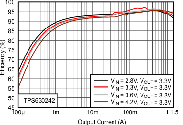
  • 在降压或升压模式中效率高达 95%,而在 VIN = VOUT 时,效率高达 97%
  • 2.5MHz 典型开关频率
  • 运行静态电流 35μA
  • 集成软启动
  • 省电模式
  • 真正关断功能
  • 输出电容器放电功能
  • 过热保护和过流保护
  • 宽电容值选择
  • 小型 1.766mm x 2.086mm,20 引脚晶圆级芯片尺寸 (WCSP) 封装

2 应用范围

  • 手机、智能电话
  • 平板个人电脑
  • 个人电脑和智能手机配件
  • 负载点稳压
  • 电池供电类 应用

3 说明

TPS63024 是一款高效、低静态电流降压-升压转换器,此转换器适用于输入电压会高于或低于输出的应用。在升压模式下,输出电流可高达 1.5A,而在降压模式下,输出电流可高达 3A。开关内的最大平均电流被限制在 3A(典型值)。TPS63024 根据输入电压在降压或升压模式之间自动切换,以便在整个输入电压范围内调节输出电压,从而确保两个模式间的无缝转换。此降压-升压转换器基于一个使用同步整流的固定频率、脉宽调制 (PWM) 控制器以获得最高效率。在低负载电流情况下,此转换器进入省电模式,以便在整个负载电流范围内保持高效率。有一个使用户能够在自动 PFM/PWM 模式运行和强制 PWM 运行之间进行选择的 PFM/PWM 引脚。在 PWM 模式期间,通常使用一个 2.5MHz 的固定频率。使用一个外部电阻分压器可对输出电压进行编程,或者在芯片上对输出电压进行内部固定。转换器可被禁用以最大限度地减少电池消耗。在关机期间,负载从电池上断开。此器件采用 20 引脚,1.766mm x 2.086 mm,WCSP 封装。

器件信息(1)

器件型号 封装 封装尺寸(标称值)
TPS63024 芯片尺寸球状引脚栅格阵列 (DSBGA) (20) 1.766mm x 2.086mm
TPS630241
TPS630242
  1. 如需了解所有可用封装,请参阅产品说明书末尾的可订购产品附录。

器件比较

器件编号 VOUT
TPS63024 可调节
TPS630241 2.9V
TPS630242 3.3 V

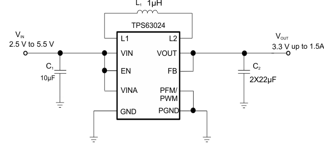
典型应用

TPS63024 TPS630241 TPS630242 schematicfront7.gif

效率与输出电流间的关系

TPS63024 TPS630241 TPS630242 Figure2rev1_SLVSCK8.gif

4 修订历史记录

Changes from * Revision (November 2014) to A Revision

  • Added Specifications, Detailed Description section, Application and Implementation section, Power Supply Recommendations section, Layout section, Device and Documentation Support section; and, changed status to Production Data. Go

5 Pin Configuration and Functions

WCSP
20-Pin
YFF (TOP VIEW)
TPS63024 TPS630241 TPS630242 TPS63025pinout2.gif

Pin Functions

PIN I/O DESCRIPTION
NAME NO.
VOUT A1,A2,A3 PWR Buck-boost converter output
FB A4 IN Voltage feedback of adjustable version, must be connected to VOUT for fixed output voltage versions
L2 B1,B2,B3 PWR Connection for Inductor
PFM/PWM B4 IN set low for PFM mode, set high for forced PWM mode. It must not be left floating
PGND C1,C2,C3 PWR Power Ground
GND C4 PWR Analog Ground
L1 D1,D2,D3 PWR Connection for Inductor
EN D4 IN Enable input. Set high to enable and low to disable. It must not be left floating.
VIN E1,E2,E3 PWR Supply voltage for power stage
VINA E4 PWR Supply voltage for control stage.

6 Specifications

6.1 Absolute Maximum Ratings(4)

over junction temperature range (unless otherwise noted)
VALUE
MIN MAX UNIT
Voltage(1) VIN, L1, EN, VINA, PFM/PWM –0.3 7 V
VOUT, FB –0.3 4 V
L2(2) –0.3 4 V
L2(3) -0.3 5.5 V
Input current Continuos average current into L1(5) 2.7 A
TJ Operating junction temperature –40 125 °C
Tstg Storage temperature range –65 150
(1) All voltage values are with respect to network ground pin.
(2) DC voltage rating.
(3) AC transient voltage rating.
(4) Stresses beyond those listed under Absolute Maximum Ratings may cause permanent damage to the device. These are stress ratings only, which do not imply functional operation of the device at these or any other conditions beyond those indicated under Recommended Operating Conditions. Exposure to absolute-maximum-rated conditions for extended periods may affect device reliability.
(5) Maximum continuos average input current 3.5A, under those condition do not exceed 105°C for more than 25% operating time.

6.2 ESD Ratings

VALUE UNIT
V(ESD) Electrostatic discharge Human-body model (HBM), per ANSI/ESDA/JEDEC JS-001(1) ±2000 V
Charged-device model (CDM), per JEDEC specification JESD22-C101(2) ±700
(1) JEDEC document JEP155 states that 500-V HBM allows safe manufacturing with a standard ESD control process.
(2) JEDEC document JEP157 states that 250-V CDM allows safe manufacturing with a standard ESD control process.

6.3 Recommended Operating Conditions(1)

MIN TYP MAX UNIT
VIN Input Voltage Range 2.3 5.5 V
VOUT Output Voltage 2.5 3.6 V
L Inductance (3) 0.5 1 1.3 µH
Cout Output Capacitance(2) 16 µF
TA Operating ambient temperature –40 85 °C
TJ Operating virtual junction temperature –40 125 °C
(1) Refer to the Application Information section for further information
(2) Due to the dc bias effect of ceramic capacitors, the effective capacitance is lower then the nominal value when a voltage is applied. This is why the capacitance is specified to allow the selection of the nominal capacitor required with the dc bias effect for this type of capacitor. The nominal value given matches a typical capacitor to be chosen to meet the minimum capacitance required.
(3) Effective inductance value at operating condition. The nominal value given matches a typical inductor to be chosen to meet the inductance required.

6.4 Thermal Information

THERMAL METRIC(1) TPS63024x UNIT
YFF
20 PINS
RθJA Junction-to-ambient thermal resistance 53.8 °C/W
RθJC(top) Junction-to-case (top) thermal resistance 0.5
RθJB Junction-to-board thermal resistance 10.1
ψJT Junction-to-top characterization parameter 1.4
ψJB Junction-to-board characterization parameter 9.8
RθJC(bot) Junction-to-case (bottom) thermal resistance N/A
(1) For more information about traditional and new thermal metrics, see the IC Package Thermal Metrics application report, SPRA953.

6.5 Electrical Characteristics

VIN=2.3V to 5.5V, TJ= –40°C to 125°C, typical values are at TA=25°C (unless otherwise noted)
PARAMETER TEST CONDITIONS MIN TYP MAX UNIT
SUPPLY
VIN Input voltage range 2.3 5.5 V
VIN_Min Minimum input voltage to turn on into full load RLOAD= 2.2Ω 2.7 V
IQ Quiescent current VIN IOUT=0mA, EN=VIN=3.6V, VOUT=3.3V TJ=-40°C to 85°C, not switching 35 70 μA
VOUT 12 μA
Isd Shutdown current EN=low, TJ=-40°C to 85°C 0.1 2 μA
UVLO Under voltage lockout threshold VIN falling 1.6 1.7 2 V
Under voltage lockout hysteresis 70 mV
Thermal shutdown Temperature rising 140 °C
LOGIC SIGNALS EN, PFM/PWM
VIH High level input voltage VIN=2.3V to 5.5V 1.2 V
VIL Low level input voltage VIN=2.3V to 5.5V 0.4 V
Ilkg Input leakage current PFM/PWM, EN=GND or VIN 0.01 0.2 μA
OUTPUT
VOUT Output Voltage range 2.5 3.6 V
VFB Feedback regulation voltage TPS63024 0.8 V
VFB Feedback voltage accuracy PWM mode, TPS63024 -1% 1%
VFB Feedback voltage accuracy (2) PFM mode, TPS63024 -1% 1.3% +3%
VOUT Output voltage accuracy PWM mode, TPS630241 2.871 2.9 2.929 V
VOUT Output voltage accuracy(2) PFM mode, TPS630241 2.871 2.938 2.987 V
VOUT Output voltage accuracy PWM mode, TPS630242 3.267 3.3 3.333 V
VOUT Output voltage accuracy(2) PFM mode, TPS630242 3.267 3.343 3.399 V
IPWM/PFM Output current to enter PFM mode VIN =3V; VOUT = 3.3V 350 mA
IFB Feedback input bias current VFB = 0.8V 10 100 nA
RDS_Buck(on) High side FET on-resistance VIN=3.0V, VOUT=3.3V 35 mΩ
Low side FET on-resistance VIN=3.0V, VOUT=3.3V 50 mΩ
RDS_Boost(on) High side FET on-resistance VIN=3.0V, VOUT=3.3V 25 mΩ
Low side FET on-resistance VIN=3.0V, VOUT=3.3V 50 mΩ
IIN Average input current limit (1) VIN=3.0V, VOUT=3.3V TJ= 25°C to 125°C 2.12 3 3.54 A
fs Switching Frequency 2.5 MHz
RON_DISC Discharge ON-Resistance EN=low 120 Ω
Line regulation VIN=2.8V to 5.5V, IOUT=1.5A 7.4 mV/V
Load regulation VIN=3.6V,IOUT=0A to 1.5A 2.5 mV/A
(1) For variation of this parameter with Input voltage and temperature see Figure 8. To calculate minimum output current in a specific working point see Figure 8 and Equation 1 trough Equation 4.
(2) Conditions: L=1 µH, COUT= 2 × 22µF.

6.6 Timing Requirements

VIN= 2.3V to 5.5V, TJ= –40°C to 125°C, typical values are at TA= 25°C (unless otherwise noted)
PARAMETER TEST CONDITIONS MIN TYP MAX UNIT
OUTPUT
tSS Softstart time EN=low to high, Buck mode VIN=3.6V, VOUT=3.3V, IOUT=1.5A 450 µs
EN=low to high, Boost mode VIN=2.8V, VOUT=3.3V, IOUT=1.5A 700 µs
td Start up delay Time from when EN=high to when device starts switching 100 µs

6.7 Typical Characteristics

.

.

TPS63024 TPS630241 TPS630242 Figure1rev2_SLVSCK8.gif
Figure 1. High Side FET On-Resistance vs VIN
TPS63024 TPS630241 TPS630242 figure1rev1_SLVSCK8.gif
Figure 2. Quiescent Current vs Input Voltage

7 Detailed Description

7.1 Overview

The TPS63024x use 4 internal N-channel MOSFETs to maintain synchronous power conversion at all possible operating conditions. This enables the device to keep high efficiency over the complete input voltage and output power range. To regulate the output voltage at all possible input voltage conditions, the device automatically switches from buck operation to boost operation and back as required by the configuration. It always uses one active switch, one rectifying switch, one switch is held on, and one switch held off. Therefore, it operates as a buck converter when the input voltage is higher than the output voltage, and as a boost converter when the input voltage is lower than the output voltage. There is no mode of operation in which all 4 switches are switching at the same time. Keeping one switch on and one switch off eliminates their switching losses. The RMS current through the switches and the inductor is kept at a minimum, to minimize switching and conduction losses. Controlling the switches this way allows the converter to always keep higher efficiency.

The device provides a seamless transition from buck to boost or from boost to buck operation.

7.2 Functional Block Diagram

TPS63024 TPS630241 TPS630242 Backup_of_TPS63025_adj_output.gif Figure 3. Functional Block Diagram (Adjustable Output Voltage)
TPS63024 TPS630241 TPS630242 TPS63025_fixed1_output.gif Figure 4. Functional Block Diagram (Fixed Output Voltage)

7.3 Feature Description

7.3.1 Undervoltage Lockout (UVLO)

To avoid mis-operation of the device at low input voltages, an undervoltage lockout is included. UVLO shuts down the device at input voltages lower than typically 1.7V with a 70 mV hysteresis.

7.3.2 Output Discharge Function

When the device is disabled by pulling enable low and the supply voltage is still applied, the internal transistor use to discharge the output capacitor is turned on, and the output capacitor is discharged until UVLO is reached. This means, if there is no supply voltage applied the output discharge function is also disabled. The transistor which is responsible of the discharge function, when turned on, operates like an equivalent 120Ω resistor, ensuring typically less than 10ms discharge time for 20uF output capacitance and a 3.3V output.

7.3.3 Thermal Shutdown

The device goes into thermal shutdown once the junction temperature exceeds typically 140°C.

7.3.4 Softstart

To minimize inrush current and output voltage overshoot during start up, the device has a Softstart. At turn on, the input current raises monotonically until the output voltage reaches regulation. During Softstart, the input current follows the current ramp charging the internal Softstart capacitor. The device smoothly ramps up the input current bringing the output voltage to its regulated value even if a large capacitor is connected at the output.

The Softstart time is measured as the time from when the EN pin is asserted to when the output voltage has reached 90% of its nominal value. There is typically a 100µs delay time from when the EN pin is asserted to when the device starts the switching activity. The Softstart time depends on the load current, the input voltage, and the output capacitor. The Softstart time in boost mode is longer then the time in buck mode. The total typical Softstart time is 1ms.

The inductor current is able to increase and always assure a soft start unless a real short circuit is applied at the output.

7.3.5 Short Circuit Protection

The TPS63024x provides short circuit protection to protect itself and the application. When the output voltage does not increase above 1.2V, the device assumes a short circuit at the output and limits the input current to 3A.

7.4 Device Functional Modes

7.4.1 Control Loop Description

TPS63024 TPS630241 TPS630242 Averagecurrent_mode_rev5.gif Figure 5. Average Current Mode Control

The controller circuit of the device is based on an average current mode topology. The average inductor current is regulated by a fast current regulator loop which is controlled by a voltage control loop. Figure 5 shows the control loop.

The non inverting input of the transconductance amplifier, gmv, is assumed to be constant. The output of gmv defines the average inductor current. The inductor current is reconstructed by measuring the current through the high side buck MOSFET. This current corresponds exactly to the inductor current in boost mode. In buck mode the current is measured during the on time of the same MOSFET. During the off time, the current is reconstructed internally starting from the peak value at the end of the on time cycle. The average current and the feedback from the error amplifier gmv forms the correction signal gmc. This correction signal is compared to the buck and the boost sawtooth ramp giving the PWM signal. Depending on which of the two ramps the gmc output crosses either the Buck or the Boost stage is initiated. When the input voltage is close to the output voltage, one buck cycle is always followed by a boost cycle. In this condition, no more than three cycles in a row of the same mode are allowed. This control method in the buck-boost region ensures a robust control and the highest efficiency.

7.4.2 Power Save Mode Operation

TPS63024 TPS630241 TPS630242 PFMPWM2.gif Figure 6. Power Save Mode Operation

Depending on the load current, in order to provide the best efficiency over the complete load range, the device works in PWM mode at load currents of approximately 350 mA or higher. At lighter loads, the device switches automatically into Power Save Mode to reduce power consumption and extend battery life. The PFM/PWM pin is used to select between the two different operation modes. To enable Power Save Mode, the PFM/PWM pin must be set low.

During Power Save Mode, the part operates with a reduced switching frequency and lowest supply current to maintain high efficiency. The output voltage is monitored with a comparator at every clock cycle by the thresholds comp low and comp high. When the device enters Power Save Mode, the converter stops operating and the output voltage drops. The slope of the output voltage depends on the load and the output capacitance. When the output voltage reaches the comp low threshold, at the next clock cycle the device ramps up the output voltage again, by starting operation. Operation can last for one or several pulses until the comp high threshold is reached. At the next clock cycle, if the load is still lower than about 350mA, the device switches off again and the same operation is repeated. Instead, if at the next clock cycle, the load is above 350mA, the device automatically switches to PWM mode.

In order to keep high efficiency in PFM mode, there is only one comparator active to keep the output voltage regulated. The AC ripple in this condition is increased, compared to the PWM mode. The amplitude of this voltage ripple in the worst case scenario is 50mV pk-pk, (typically 30mV pk-pk), with 20µF effective output capacitance. In order to avoid a critical voltage drop when switching from 0A to full load, the output voltage in PFM mode is typically 1.3% above the nominal value in PWM mode. This is called Dynamic Voltage Positioning and allows the converter to operate with a small output capacitor and still have a low absolute voltage drop during heavy load transients.

Power Save Mode is disabled by setting the PFM/PWM pin high.

7.4.3 Current Limit

The current limit variation depends on the difference between the input and output voltage. The maximum current limit value is at the highest difference.

Given the curves provided in Figure 8, it is possible to calculate the output current reached in boost mode, using Equation 1 and Equation 2 and in buck mode using Equation 3 and Equation 4.

Equation 1. TPS63024 TPS630241 TPS630242 q1_boost_lvsa92.gif
Equation 2. TPS63024 TPS630241 TPS630242 q1_boost_lvsa92[1].gif
Equation 3. TPS63024 TPS630241 TPS630242 q3_buck_lvsa92.gif
Equation 4. TPS63024 TPS630241 TPS630242 q1_buck_lvsa92[1].gif

where

  • η = Estimated converter efficiency (use the number from the efficiency curves or 0.90 as an assumption)
  • IIN= Minimum average input current (Figure 8)

7.4.4 Supply and Ground

The TPS63024x provides two input pins (VIN and VINA) and two ground pins (PGND and GND).

The VIN pin supplies the input power, while the VINA pin provides voltage for the control circuits. A similar approach is used for the ground pins. GND and PGND are used to avoid ground shift problems due to the high currents in the switches. The reference for all control functions is the GND pin. The power switches are connected to PGND. Both grounds must be connected on the PCB at only one point, ideally, close to the GND pin.

7.4.5 Device Enable

The device starts operation when the EN pin is set high. The device enters shutdown mode when the EN pin is set low. In shutdown mode, the regulator stops switching, all internal control circuitry is switched off, and the load is disconnected from the input.

8 Application and Implementation

NOTE

Information in the following applications sections is not part of the TI component specification, and TI does not warrant its accuracy or completeness. TI’s customers are responsible for determining suitability of components for their purposes. Customers should validate and test their design implementation to confirm system functionality.

8.1 Application Information

The TPS63024x are high efficiency, low quiescent current buck-boost converters suitable for application where the input voltage is higher, lower or equal to the output. Output currents can go as high as 1.5A in boost mode and as high as 3A in buck mode. The maximum average current in the switches is limited to a typical value of 3A.

8.2 Typical Application

TPS63024 TPS630241 TPS630242 schematic11.gif Figure 7. 3.3-V Adjustable Version

8.2.1 Design Requirements

The design guideline provides a component selection to operate the device within the recommended operating conditions.

Table 1 shows the list of components for the Application Characteristic Curves.

Table 1. Components for Application Characteristic Curves(1)

REFERENCE DESCRIPTION MANUFACTURER
TPS63024 Texas Instruments
L1 1 μH, 8.75A, 13mΩ, SMD XAL4020-102MEB, Coilcraft
C1 10 μF 6.3V, 0603, X5R ceramic Standard
C2,C3 22 μF 6.3V, 0603, X5R ceramic Standard
R1 560kΩ Standard
R2 180kΩ Standard
(1) See Third-Party Products Discalimer

8.2.2 Detailed Design Procedure

The first step is the selection of the output filter components. To simplify this process Table 2 outline possible inductor and capacitor value combinations.

8.2.2.1 Output Filter Design

Table 2. Matrix of Output Capacitor and Inductor Combinations

NOMINAL INDUCTOR
VALUE [µH](1)
NOMINAL OUTPUT CAPACITOR VALUE [µF](2)
44 47 66 88 100
0.680 + + +
1.0 +(3) + + + +
1.5 + + +
(1) Inductor tolerance and current de-rating is anticipated. The effective inductance can vary by 20% and –30%.
(2) Capacitance tolerance and bias voltage de-rating is anticipated. The effective capacitance can vary by 20% and –50%.
(3) Typical application. Other check mark indicates recommended filter combinations

8.2.2.2 Inductor Selection

The inductor selection is affected by several parameter like inductor ripple current, output voltage ripple, transition point into Power Save Mode, and efficiency. See Table 3 for typical inductors.

Table 3. List of Recommended Inductors(1)

INDUCTOR VALUE COMPONENT SUPPLIER SIZE (LxWxH mm) Isat/DCR
1 µH Coilcraft XAL4020-102ME 4 X 4 X 2.10 4.5A/10mΩ
1 µH Toko, DFE322512C 3.2 X 2.5 X 1.2 4.7A/34mΩ
1 µH TDK, SPM4012 4.4 X 4.1 X 1.2 4.1A/38mΩ
1 µH Wuerth, 74438334010 3 X 3 X 1.2 6.6A/42.10mΩ
0.6 µH Coilcraft XFL4012-601ME 4 X 4 X 1.2 5A/17.40mΩ
0.68µH Wuerth,744383340068 3 X 3 X 1.2 7.7A/36mΩ
(1) See Third-Party Products Desclaimer

For high efficiencies, the inductor should have a low dc resistance to minimize conduction losses. Especially at high-switching frequencies, the core material has a high impact on efficiency. When using small chip inductors, the efficiency is reduced mainly due to higher inductor core losses. This needs to be considered when selecting the appropriate inductor. The inductor value determines the inductor ripple current. The larger the inductor value, the smaller the inductor ripple current and the lower the conduction losses of the converter. Conversely, larger inductor values cause a slower load transient response. To avoid saturation of the inductor, the peak current for the inductor in steady state operation is calculated using Equation 6. Only the equation which defines the switch current in boost mode is shown, because this provides the highest value of current and represents the critical current value for selecting the right inductor.

Equation 5. TPS63024 TPS630241 TPS630242 q1_boost_lvsa92.gif
Equation 6. TPS63024 TPS630241 TPS630242 peak_current_boost_lvsa92.gif

where

  • D =Duty Cycle in Boost mod
  • ƒ = Converter switching frequency (typical 2.5MHz)
  • L = Inductor value
  • η = Estimated converter efficiency (use the number from the efficiency curves or 0.90 as an assumption)
  • Note: The calculation must be done for the minimum input voltage which is possible to have in boost mode

Calculating the maximum inductor current using the actual operating conditions gives the minimum saturation current of the inductor needed. It's recommended to choose an inductor with a saturation current 20% higher than the value calculated using Equation 6. Possible inductors are listed in Table 3.

8.2.2.3 Capacitor Selection

8.2.2.3.1 Input Capacitor

At least a 10μF input capacitor is recommended to improve line transient behavior of the regulator and EMI behavior of the total power supply circuit. An X5R or X7R ceramic capacitor placed as close as possible to the VIN and PGND pins of the IC is recommended. This capacitance can be increased without limit. If the input supply is located more than a few inches from the TPS63024x converter additional bulk capacitance may be required in addition to the ceramic bypass capacitors. An electrolytic or tantalum capacitor with a value of 47 μF is a typical choice.

8.2.2.3.2 Output Capacitor

For the output capacitor, use of a small ceramic capacitors placed as close as possible to the VOUT and PGND pins of the IC is recommended. The recommended nominal output capacitance value is 20 µF with a variance as outlined in Table 2.

There is also no upper limit for the output capacitance value. Larger capacitors causes lower output voltage ripple as well as lower output voltage drop during load transients.

8.2.2.4 Setting The Output Voltage

When the adjustable output voltage version TPS63024x is used, the output voltage is set by an external resistor divider. The resistor divider must be connected between VOUT, FB and GND. When the output voltage is regulated properly, the typical value of the voltage at the FB pin is 800mV. The current through the resistive divider should be about 10 times greater than the current into the FB pin. The typical current into the FB pin is 0.1μA, and the voltage across the resistor between FB and GND, R2, is typically 800 mV. Based on these two values, the recommended value for R2 should be lower than 180kΩ, in order to set the divider current at 4μA or higher. It is recommended to keep the value for this resistor in the range of 180kΩ. From that, the value of the resistor connected between VOUT and FB, R1, depending on the needed output voltage (VOUT), can be calculated using Equation 7:

Equation 7. TPS63024 TPS630241 TPS630242 qr1r2_lvs916.gif

8.2.3 Application Curves

TPS63024 TPS630241 TPS630242 MaxCurrent3_SLVSCK8.gif
VOUT = 3.3 V
Figure 8. Minimum Average Input Current vs Input Voltage
TPS63024 TPS630241 TPS630242 Figure3rev1_SLVSCK8.gif
PFM/PWM = High
Figure 10. Efficiency vs Output Current
TPS63024 TPS630241 TPS630242 Figure2rev1_SLVSCK8.gif
PFM/PWM = Low
Figure 9. Efficiency vs Output Current
TPS63024 TPS630241 TPS630242 Figure4rev1_SLVSCK8.gif
PFM/PWM = Low
Figure 11. Efficiency vs Output Current
TPS63024 TPS630241 TPS630242 Figure6rev2_SLVSCK8.gif
PFM/PWM = Low VOUT = 3.3 V
Figure 13. Efficiency vs Input Voltage
TPS63024 TPS630241 TPS630242 Figure5rev1_SLVSCK8.gif
PFM/PWM = High
Figure 12. Efficiency vs Output Current
TPS63024 TPS630241 TPS630242 Figure7rev1_SLVSCK8.gif
PFM/PWM = High VOUT = 3.3 V
Figure 14. Efficiency vs Input Voltage
TPS63024 TPS630241 TPS630242 Figure8rev1_SLVSCK8.gif
PFM/PWM = Low VOUT = 2.9 V
Figure 15. Efficiency vs Input Voltage
TPS63024 TPS630241 TPS630242 Figure19rev24_SLVSCK8.gif
PFM/PWM = Low
Figure 17. Output Voltage vs Output Current
TPS63024 TPS630241 TPS630242 Figure14_SLVSCK8.gif
VIN = 3.3 V IOUT = 290 mA
Figure 19. Output Voltage Ripple in Buck-Boost Mode
and PFM to PWM Transition
TPS63024 TPS630241 TPS630242 Figure9rev1_SLVSCK8.gif
PFM/PWM = High VOUT = 2.9 V
Figure 16. Efficiency vs Input Voltage
TPS63024 TPS630241 TPS630242 Figure20rev4_SLVSCK8.gif
PFM/PWM = High
Figure 18. Output Voltage vs Output Current
TPS63024 TPS630241 TPS630242 Figure15_SLVSCK8.gif
VIN = 2.8 V IOUT = 16 mA
Figure 20. Output Voltage Ripple in Boost Mode and PFM Operation
TPS63024 TPS630241 TPS630242 Figure16_SLVSCK8.gif
VIN = 4.2 V IOUT = 16 mA
Figure 21. Output Voltage Ripple in Buck Mode
and PFM Operation
TPS63024 TPS630241 TPS630242 Figure18rev1_SLVSCK8.gif
VIN = 4.5 V IOUT = 1 A
Figure 23. Switching Waveforms in Buck Mode
and PWM Operation
TPS63024 TPS630241 TPS630242 Figure20rev1_SLVSCK8.gif
VIN = 2.8 V IOUT = 0 A to 1.5 A
Figure 25. Load Transient Response Boost Mode
TPS63024 TPS630241 TPS630242 Figure22_SLVSCK8.gif
VIN = from 3.5 V to 3.6 V IOUT = 1.5 A
Figure 27. Line Transient Response
TPS63024 TPS630241 TPS630242 Figure24_SLVSCK8.gif
VIN = 4.5 V IOUT = 0 A
Figure 29. Start Up After Enable
TPS63024 TPS630241 TPS630242 Figure17_SLVSCK8.gif
VIN = 2.5 V IOUT = 1 A
Figure 22. Switching Waveforms in Boost Mode
and PWM Operation
TPS63024 TPS630241 TPS630242 Figure19_SLVSCK8.gif
VIN = 3.3 V IOUT = 1 A
Figure 24. Switching Waveforms in Buck-Boost Mode
and PWM Operation
TPS63024 TPS630241 TPS630242 Figure21_SLVSCK8.gif
VIN = 4.2 V IOUT = 0 A to 1.5 A
Figure 26. Load Transient Response Buck Mode
TPS63024 TPS630241 TPS630242 Figure23_SLVSCK8.gif
VIN = 2.5 V IOUT = 0 A
Figure 28. Start Up After Enable


Texas Instruments

© Copyright 1995-2025 Texas Instruments Incorporated. All rights reserved.
Submit documentation feedback | IMPORTANT NOTICE | Trademarks | Privacy policy | Cookie policy | Terms of use | Terms of sale