• Menu
  • Product
  • Email
  • PDF
  • Order now
  • HD3SS460 4 x 6 通道 USB Type-C交替模式 MUX

    • ZHCSDI9D January   2015  – January 2017 HD3SS460

      PRODUCTION DATA.  

  • CONTENTS
  • SEARCH
  • HD3SS460 4 x 6 通道 USB Type-C交替模式 MUX
  1. 1 特性
  2. 2 应用
  3. 3 说明
  4. 4 修订历史记录
  5. 5 Device Comparison Table
  6. 6 Pin Configuration and Functions
  7. 7 Specifications
    1. 7.1 Absolute Maximum Ratings
    2. 7.2 ESD Ratings
    3. 7.3 Recommended Operating Conditions
    4. 7.4 Thermal Information
    5. 7.5 Electrical Characteristics
    6. 7.6 High Speed Port Performance Parameters
    7. 7.7 High Speed Signal Path Switching Characteristics
    8. 7.8 Timing Diagrams
  8. 8 Detailed Description
    1. 8.1 Overview
    2. 8.2 Functional Block Diagram
    3. 8.3 Feature Description
      1. 8.3.1 High Speed Differential Signal Switching
      2. 8.3.2 Low Speed SBU Signal Switching
      3. 8.3.3 Output Enable and Power Savings
    4. 8.4 Device Functional Modes
      1. 8.4.1 Device High Speed Switch Control Modes
  9. 9 Application and Implementation
    1. 9.1 Application Information
    2. 9.2 USB SS and DP as Alternate Mode
      1. 9.2.1 Design Requirements
      2. 9.2.2 Detailed Design Procedure
  10. 10Power Supply Recommendations
  11. 11Layout
    1. 11.1 Layout Guidelines
      1. 11.1.1 Critical Routing
      2. 11.1.2 General Routing/Placement Rules
    2. 11.2 Layout Example
  12. 12器件和文档支持
    1. 12.1 接收文档更新通知
    2. 12.2 社区资源
    3. 12.3 商标
    4. 12.4 静电放电警告
    5. 12.5 Glossary
  13. 13机械、封装和可订购信息
  14. 重要声明
search No matches found.
  • Full reading width
    • Full reading width
    • Comfortable reading width
    • Expanded reading width
  • Card for each section
  • Card with all content


DATA SHEET

HD3SS460 4 x 6 通道 USB Type-C交替模式 MUX

本资源的原文使用英文撰写。 为方便起见,TI 提供了译文;由于翻译过程中可能使用了自动化工具,TI 不保证译文的准确性。 为确认准确性,请务必访问 ti.com 参考最新的英文版本(控制文档)。

1 特性

  • 提供面向 USB Type-CTM 生态系统的 MUX 解决方案,其中包括交替模式 (AM)
  • 提供多种通道选择选项,其中包括 USBSS、双通道 AM 和四通道 AM
  • 与 5 Gbps USB3.1 第 1 代和包含 5.4 Gbps DisplayPort 1.2a 的 AM 兼容
  • 与源设备/主机和接收设备/设备应用 兼容
  • 针对低速 SBU 引脚提供交叉点 MUX
  • 双向“复用/解复用”差动开关
  • 支持 0V 至 2V 共模电压
  • 功耗较低,关断电流和工作电流分别为 1μA 和 0.6mA
  • 单电源电压 VCC:3.3V±10%
  • 工业温度范围:–40°C 至 85°C

2 应用

  • 可换向 USB Type-CTM 生态系统
  • 平板电脑、笔记本电脑、监视器、电话
  • USB 主机和设备
  • 扩展坞

3 说明

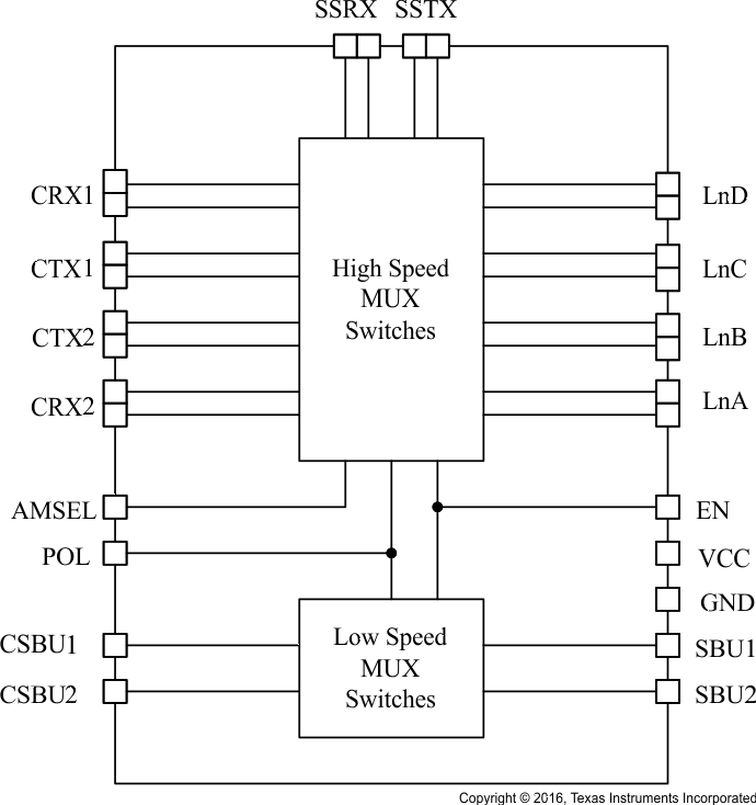
HD3SS460 是一款高速双向无源开关,可采用复用或解复用两种配置。该器件可通过负载点 (POL) 控制引脚进行切换,从而适应连接器换向。该器件还可通过 AMSEL 控制引脚来实现双通道数据/双通道视频与所有四通道视频的复用。

该器件还针对低速引脚提供了交叉点 MUX,可满足可换向连接器实现的需求。

HD3SS460 是一款通用模拟差分无源开关,适用于所有高速接口 应用, 前提条件是该应用在 0V 至 2V 共模电压范围内发生偏置并且具有幅值高达 1800 mVpp 的差分信令。该器件采用自适应跟踪,可确保信道在整个共模电压范围内保持不变。

该器件具有出色的动态特性,可在信号眼图衰减最小的情况下实现高速转换,并且附加抖动极少。该器件在工作模式下的功耗 < 2mW,关断模式下的功耗 < 5µW(可通过 EN 引脚切换模式)。

器件信息(1)

器件型号 封装 封装尺寸(标称值)
HD3SS460 QFN (RHR) (28) 3.50mm x 5.50mm
HD3SS460I
HD3SS460 QFN (RNH) (30) 2.50mm x 4.50mm
HD3SS460I
  1. 要了解所有可用封装,请见数据表末尾的可订购产品附录。

sp

简化电路原理图

HD3SS460 FP_schem_SLLSEM7.gif

应用

HD3SS460 FP_application_SLLSEM7.gif

4 修订历史记录

Changes from C Revision (December 2016) to D Revision

  • Deleted R187 from Figure 16 Go
  • Deleted R187 from Figure 19.Go

Changes from B Revision (June 2016) to C Revision

  • 已将 QFN (RNH) (30) 添加至器件信息表Go
  • Added the RNH package option to the Device Comparison Table tableGo
  • Added the RNH package option to the Pin Configuration and Functions sectionGo
  • Changed the Description of pins LnBn, p, LnCn, p, LnDn, p, SSTXn, p, and SSRXn, p From: positive, negative To: negative, positive in the Pin Functions tableGo
  • Changed the Supply voltage MIN value From: 3.0 V To: 2.7 V in the Recommended Operating Conditions tableGo
  • Added the RNH package option to the Thermal Information table Go
  • Changed VIH to include a separate line entry for POL pin in the Electrical Characteristics tableGo

Changes from A Revision (March 2015) to B Revision

  • Changed text and Figure 3, Figure 4 in the USB SS and DP as Alternate Mode section for clarity. Go
  • Added Figure 5Go
  • Added Figure 6Go
  • Deleted Table Pin Assignments for DP Source Pins and DP Sink Pins in the Detailed Design Procedure sectionGo
  • Added Table 2, Table 3, Table 4, and Table 5 Go
  • Added Figure 8 through Figure 13 Go
  • Changed image for Figure 16 Go
  • Changed image for Figure 19.Go

Changes from * Revision (January 2015) to A Revision

  • Added full data sheet specification complement Go

5 Device Comparison Table(1)

OPERATING TEMPERATURE (°C) PART NUMBER PINS TOP-SIDE MARKING
0 to 70 HD3SS460RHR 28 3SS460
–40 to 85 HD3SS460IRHR 28 3SS460I
0 to 70 HD3SS460RNH 30 460RNH
–40 to 85 HD3SS460IRNH 30 460IRNH
(1) For all available packages, see the orderable addendum at the end of the data sheet. Package drawings, thermal data, and symbolization are available at www.ti.com/packaging

6 Pin Configuration and Functions

RHR Package With Thermal Pad
(28-Pin WQFN)
Top View
HD3SS460 RHR_pinout_SLLSEM7.gif
RNH Package With Thermal Pad
(30-Pin WQFN)
Top View
HD3SS460 RNH_pinout_SLLSEM7.gif

Pin Functions

PIN TYPE(1) DESCRIPTION
NAME RHR
NO.
RNH
NO.
VCC 22 23 P Power
GND PAD 13, 28, PAD G Ground
POL 3 3 Input Provides MUX control (Table 1)
AMSEL 8 8 3-Level Input Provides MUX configurations (Table 1)
EN 17 18 3-Level Input Enable signal; also provides MUX control (Table 1)
CRX1p, n 1, 2 1, 2 I/O High Speed Signal Port CRX1 positive, negative
CTX1p, n 4, 5 4, 5 I/O High Speed Signal Port CTX1 positive, negative
CTX2p, n 6, 7 6, 7 I/O High Speed Signal Port CTX2 positive, negative
CRX2p, n 9, 10 9, 10 I/O High Speed Signal Port CRX2 positive, negative
LnAn, p 15, 16 16, 17 I/O High Speed Signal Port LnA positive, negative
LnBn, p 18, 19 19, 20 I/O High Speed Signal Port LnB negative, positive
LnCn, p 20, 21 21, 22 I/O High Speed Signal Port LnC negative, positive
LnDn, p 23, 24 24, 25 I/O High Speed Signal Port LnD negative, positive
SSTXn, p 25, 26 26, 27 I/O High Speed Signal Port SSTX negative, positive
SSRXn, p 27, 28 29, 30 I/O High Speed Signal Port SSRX negative, positive
CSBU1, 2 11, 12 11, 12 I/O Low Speed Signal Port CSBU 1, 2
SBU1, 2 13, 14 14, 15 I/O Low Speed Signal Port SBU 1, 2
(1) High speed data ports (CRX[1/2][p/n], Ln[A-D][p,n], and SS[T/R]X[p/n]) incorporate 20kΩ pull down resistors that are switched in when a port is not selected and switched out when the port is selected.

7 Specifications

7.1 Absolute Maximum Ratings

over operating free-air temperature range (unless otherwise noted) (1)
MIN MAX UNIT
Supply Voltage, VCC –0.5 4 V
Differential High Speed I/O Voltages, C[R/T]X[1/2][p/n], Ln[A-D][p/n], SS[R/T]X[p/n] –0.5 2.5 V
Low Speed I/O Voltages, CSBU[1/2], SBU[1/2] –0.5 4 V
Control signal voltages, POL, AMSEL, EN –0.5 4 V
Storage temperature, Tstg –65 150 °C
(1) Stresses beyond those listed under Absolute Maximum Ratings may cause permanent damage to the device. These are stress ratings only, which do not imply functional operation of the device at these or any other conditions beyond those indicated under Recommended Operating Conditions. Exposure to absolute-maximum-rated conditions for extended periods may affect device reliability.

7.2 ESD Ratings

VALUE UNIT
V(ESD) Electrostatic discharge Human-body model (HBM), per ANSI/ESDA/JEDEC JS-001(1) ±4000 V
Charged-device model (CDM), per JEDEC specification JESD22-C101(2) ±1000 V
(1) JEDEC document JEP155 states that 500-V HBM allows safe manufacturing with a standard ESD control process. Manufacturing with less than 500-V HBM is possible with the necessary precautions.
(2) JEDEC document JEP157 states that 250-V CDM allows safe manufacturing with a standard ESD control process. Manufacturing with less than 250-V CDM is possible with the necessary precautions.

7.3 Recommended Operating Conditions

over operating free-air temperature range (unless otherwise noted)
MIN NOM MAX UNIT
VCC Supply voltage 2.7 3.3 3.6 V
TA Operating free air temperature HD3SS460 0 25 70 °C
HD3SS460I –40 25 85
VCM High speed port common mode voltage 0 2 V
VIN Low Speed signal voltage 0 VCC
Vdiff High speed port differential voltage 0 1.8 Vpp

7.4 Thermal Information

THERMAL METRIC(1) HD3SS460 UNIT
QFN (RNH) QFN (RHR)
30 PINS 28 PINS
RθJA Junction-to-ambient thermal resistance 51.6 44.0 °C/W
RθJC(top) Junction-to-case (top) thermal resistance 37.5 34.8 °C/W
RθJB Junction-to-board thermal resistance 17.5 14.7 °C/W
ψJT Junction-to-top characterization parameter 0.7 0.7 °C/W
ψJB Junction-to-board characterization parameter 17.3 24.5 °C/W
RθJC(bot) Junction-to-case (bottom) thermal resistance 6.8 6.9 °C/W
(1) For more information about traditional and new thermal metrics, see the Semiconductor and IC Package Thermal Metrics application report.

7.5 Electrical Characteristics

typical values for all parameters are at VDD = 3.3 V and TA = 25°C (unless otherwise noted)
PARAMETER TEST CONDITIONS MIN TYP MAX UNIT
VIL Input low voltage, control pins POL, AMSEL, EN –0.1 0.4 V
VIH Input high voltage, control pins AMSEL, EN VCC –0.4 VCC +0.1
Input high voltage, control pins POL 1.7 VCC +0.1
VIM Input mid-level voltage, control pins AMSEL, EN VCC/2 –0.3 VCC/2 VCC/2 +0.3
ILK-DIFF-ACTIVE Leakage current on active differential IO pins, VCC = 3.6 V, pin at 0 or 2.4 V. 1 µA
ILK-DIFF-INACTIVE Leakage current on inactive differential IO pins, VCC = 3.6V, pin at 2.4 V. 150
IIH Input high current, control pins POL, AMSEL, EN and signal pins CSBU1/2, SBU1/2 1
IIL Input low current, control pins POL, AMSEL, EN and signal pins CSBU1/2, SBU1/2 1
IIM Input mid-level current, control pins AMSEL, EN 1
IOFF Device shutdown current 1 5
IDD Device active current, EN=H or M 0.6 0.9 mA
RON(HS) Switch ON resistance for high speed differential signals VCC = 3.3 V, VCM = 0-2 V,
IO = - 8 mA
8 14 Ω
RON(LS) Switch ON resistance for low speed signals VCC = 3.3 V, VCM = 0-2 V,
IO = - 8 mA
12
RFLAT(ON,HS) High speed differential signals’ ON resistance flatness for a channel (RON(MAX) – RON(MIN)) over VCM range VCC = 3.3 V, VCM = 0-2 V,
IO = - 8 mA
1.5
CON(HS) High speed differential signals’ input capacitance 1 pF

7.6 High Speed Port Performance Parameters

under recommended operating conditions; RLOAD, RSC = 50 Ω (unless otherwise noted)
PARAMETER MIN TYP MAX UNIT
RL Differential return loss 100 Mhz SS Paths –23 dB
2.5 Ghz SS Paths –9
100 MHz AM Paths –23
2. 7GHz AM Paths –13
IL Differential insertion loss 100 Mhz SS Paths –0.7
2.5 Ghz SS Paths –1.6
100 MHz AM Paths –0.7
2.7 GHz AM Paths –1.4
OI Differential off isolation 100 Mhz –50
2.5 Ghz –26
2.7 GHz –25
Xtalk Differential cross talk, Between CRX1/2 and CTX1/2 100 Mhz –80
2.5 Ghz –30
2.7 Ghz –28
Differential cross talk, Between CRX1 and CRX2 or CTX1 and CTX2 100 Mhz –50
2.5 Ghz –26
2.7 Ghz –25
BWSS Differential –3 dB BW SS Paths 4.2 GHz
BWAM Differential –3 dB BW AM Paths 5.4
BWSBU Low-speed switch –3 dB BW 500 MHz

7.7 High Speed Signal Path Switching Characteristics

PARAMETER TEST CONDITION MIN TYP MAX UNIT
tPD Switch propagation delay RSC and RLOAD = 50 Ω, Figure 2 100 ps
tSK(O) Inter-Pair output skew (CH-CH) 50
tSK(b-b) Intra-Pair output skew (bit-bit) 5
tON Control signals POL, AMSEL and EN (H/M toggle) to switch ON time RSC and RLOAD = 50 Ω, Figure 1 3 µs
tOFF Control signals POL, AMSEL and EN (H/M toggle) to switch OFF time 1

7.8 Timing Diagrams

HD3SS460 Switch_on-off_time_SLLSEM7.gif Figure 1. Switch ON/OFF Time
HD3SS460 Prop_delay_skew1_SLLSEM7.gif Figure 2. Propagation Delay and Skew

8 Detailed Description

8.1 Overview

The HD3SS460 is a high-speed bi-directional passive 4-6 cross-point switch in mux or demux configurations. Based on control pin POL the device provides switching to accommodate USB Type-C plug flipping. The device provides multiple signal switching options that allow system implementation flexibility.

The HD3SS460 is a generic analog, differential passive switch that can work for any high speed interface applications as long as it is biased at a common mode voltage range of 0-2 V and has differential signaling with differential amplitude up to 1800 mVpp. It employs an adaptive tracking that ensures the channel remains unchanged for entire common mode voltage range

Excellent dynamic characteristics of the device allow high speed switching with minimum attenuation to the signal eye diagram with very little added jitter.

8.2 Functional Block Diagram

HD3SS460 FP_schem_SLLSEM7.gif

8.3 Feature Description

8.3.1 High Speed Differential Signal Switching

Based on control pin AMSEL the device provides muxing options of:

  1. 1 port (RX and TX) USB3.1 SS data / 2Ch video (or any other Alternate Mode data)
  2. All 4Ch video (or any other Alternate Mode data)
  3. 1 port (RX and TX) USB3.1 SS data
  4. 1 port (RX and TX) USB3.1 SS data / 2Ch video (or any other Alternate Mode data) with option of choosing video from two different source/sink
  5. 1 port (RX and TX) USB3.1 SS data / 2Ch video (or any other Alternate Mode data) with option of choosing video 2 Ln Video or 1 Ln Video from two different source/sink

8.3.2 Low Speed SBU Signal Switching

The device also provides cross point muxing for low speed SBU signals as needed in USB Type-C flippable connector implementation. The device provides the option to choose the USB only implementation where SBU ports are in tri-state.

8.3.3 Output Enable and Power Savings

The HD3SS460 has two power modes, active/normal operating mode and standby/shutdown mode. During standby mode, the device consumes very little current to save the maximum power. To enter standby mode, the EN control pin is pulled low and must remain low. For active/normal operation, the EN control pin should be pulled high to VDD through a resistor or dynamically controlled to switch between H or M.

HD3SS460 consumes <2 mW of power when operational and <5 µW in shutdown mode, exercisable by the EN pin.

8.4 Device Functional Modes

8.4.1 Device High Speed Switch Control Modes

Table 1. MUX Control for High Speed and Low Speed SBU Channels

POL AMSEL EN CONFIGURATIONS HIGH SPEED SIGNAL FLOW(1) SBU SIGNAL FLOW
L L H 2CH USBSS + 2CH AM (Normal)
HD3SS460 D001_SLLSEM7.gif
HD3SS460 D002_SLLSEM7.gif
H L H 2CH USBSS + 2CH AM (Flipped)
HD3SS460 D003_SLLSEM7.gif
HD3SS460 D004_SLLSEM7.gif
L H H 4CH AM (Normal)
HD3SS460 D005_SLLSEM7.gif
HD3SS460 D002_SLLSEM7.gif
H H H 4CH AM (Flipped)
HD3SS460 D006_SLLSEM7.gif
HD3SS460 D004_SLLSEM7.gif
L M H 2CH USBSS (Normal)
HD3SS460 D007_SLLSEM7.gif
All Low Speed SBU Ports HighZ
H M H 2CH USBSS (Flipped)
HD3SS460 D008_SLLSEM7.gif
All Low Speed SBU Ports HighZ
L M M 2CH USBSS + 2CH AM (Normal)
HD3SS460 D009_SLLSEM7.gif
HD3SS460 D002_SLLSEM7.gif
H M M 2CH USBSS + 2CH AM (Flipped)
HD3SS460 D010_SLLSEM7.gif
HD3SS460 D004_SLLSEM7.gif
L L M 2CH USBSS + 2CH AM from alternate GPU (Normal)
HD3SS460 D011_SLLSEM7.gif
HD3SS460 D002_SLLSEM7.gif
H L M 2CH USBSS + 2CH AM from alternate GPU (Flipped)
HD3SS460 D012_SLLSEM7.gif
HD3SS460 D004_SLLSEM7.gif
L H M Reserved Reserved Reserved
H H M Reserved Reserved Reserved
X X L All High Speed Ports HighZ All High Speed Ports HighZ All Low Speed SBU Ports HighZ
(1) All positive signals connect to positive and negative to negative

9 Application and Implementation

NOTE

Information in the following applications sections is not part of the TI component specification, and TI does not warrant its accuracy or completeness. TI’s customers are responsible for determining suitability of components for their purposes. Customers should validate and test their design implementation to confirm system functionality.

9.1 Application Information

HD3SS460 can be utilized for a wide range of muxing needs. This is general purpose passive cross-point switch. The channels have independent adaptive common mode tracking allowing flexibility. As long as recommended electrical use conditions are met the device can be used number of ways as described in Table 1.

NOTE

HD3SS460 does not provide common mode biasing for the channel. Therefore it is required that the device is biased from either side for all active channels.

9.2 USB SS and DP as Alternate Mode

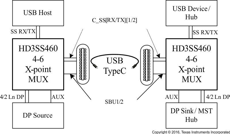
HD3SS460 can be used USB Type-C ecosystem with DP as alternate mode in two distinct application configurations – one is for DP Source/USB Host, the other one for the DP Sink/USB Device/Dock. Figure 3 and Figure 4 illustrate typical application block diagrams for these two cases. Detail schematics are illustrated in Detailed Design Procedure section. Other applications and or use cases possible where these examples can be used as general guidelines.

Figure 3 and Figure 4 depict the AC coupling capacitor placement examples. TI recommends placing the capacitors as shown in the illustrations for the backward compatibility and interoperability purposes as some of the existing USB systems may present Vcm, exceeding the typical range of 0–2 V on SS differential pairs.

HD3SS460 typ_c_interface_DP_sllsem7.gif Figure 3. Block Diagram for a Type C Interface Using DP as Alternate Mode – Source/Host
HD3SS460 nfig05_cap_place_sllem7.gif Figure 4. Diagram for a Type C Interface Using DP as Alternate Mode – Sink/Device/Dock

Figure 5 and Figure 6 depict the AC coupling capacitor recommendations in case the upstream or downstream port connected internally to the HD3SS460 presents Vcm greater than 2 V.

HD3SS460 USB_Host_DP_source_sllsem7.gif Figure 5. HD3SS460 USB Host (DP Source with SS USB Vcm)
HD3SS460 nfig07_cap_place_sllem7.gif Figure 6. HD3SS460 USB Upstream (DP Sink Implementation Example)

9.2.1 Design Requirements

DESIGN PARAMETERS EXAMPLE VALUES
VCC 3.3 V
Decoupling capacitors 0.1 µF
AC Capacitors 75-200nF (100nF shown) USBSS TX p and n lines require AC capacotprs. Alternate mode signals may or may not require AC capacitors
Control pins Controls pins can be dynamically controlled or pin-strapped. The POL signal is controlled by CC logic in the Type-C ecosystem.

9.2.2 Detailed Design Procedure

The reference schematics shown in this document are based upon the pin assignment defined in the Alternate mode over Type C specification as shown in Figure 7 below.

HD3SS460 source_sink_assign_SLLSEM7.gif Figure 7. Pin Assignment – Alternate Mode Over Type C

Table 2 represents the example pin mapping to HD3SS460 for the DP Source pin assignments C, D, E and F, DP Sink pin assignments C and D.

Table 2. SOURCE Pin Assignment Option C and E (AMSEL = H, EN = H)

RECEPTACLE PIN NUMBER 460 PIN MAPPING TO TYPE C CONNECTOR 460 PIN MAPPING TO DP SOURCE (GPU)
POL = L POL = H
A11/10 CRX2 LnA(ML0) LnD(ML3)
A2/3 CTX1 LnC(ML2) LnB(ML1)
B11/10 CRX1 LnD(ML3) LnA(ML0)
B2/3 CTX2 LnB(ML1) LnC(ML2)
A8 CSBU1 SBU1(AUXP) SBU2(AUXN)
B8 CSBU2 SBU2(AUXN) SBU1(AUXP)
HD3SS460 Diagram_Source_C_E_sllem7.gif Figure 8. SOURCE Pin Assignment Option C and E (AMSEL = H, EN = H)

Table 3. SOURCE Pin Assignment Option D and F (AMSEL = L, EN = H)

RECEPTACLE PIN NUMBER 460 PIN MAPPING TO TYPE C CONNECTOR 460 PIN MAPPING TO DP SOURCE (GPU)
POL = L POL = H
A11/10 CRX2 LnA(ML0) SSRX
A2/3 CTX1 SSTX LnB(ML1)
B11/10 CRX1 SSRX LnA(ML0)
B2/3 CTX2 LnB(ML1) SSTX
A8 CSBU1 SBU1(AUXP) SBU2(AUXN)
B8 CSBU2 SBU2(AUXN) SBU1(AUXP)

Space

HD3SS460 Diagram_Source_D_F_POLL_sllem7.gif Figure 9. SOURCE Pin Assignment Option D and F (AMSEL = L, EN = H, POL = L)
HD3SS460 Diagram_Source_D_F_POLH_sllem7.gif Figure 10. SOURCE Pin Assignment Option D and F (AMSEL = L, EN = H, POL = H)

Table 4. SINK Pin Assignment Option C (AMSEL = H, EN = H)

RECEPTACLE PIN NUMBER 460 PIN MAPPING TO TYPE C CONNECTOR 460 PIN MAPPING TO DP SOURCE (GPU)
POL = L POL = H
A11/10 CRX2 LnA(ML1) LnD(ML2)
A2/3 CTX1 LnC(ML3) LnB(ML0)
B11/10 CRX1 LnD(ML2) LnA(ML1)
B2/3 CTX2 LnB(ML0) LnC(ML3)
A8 CSBU1 SBU1(AUXN) SBU2(AUXP)
B8 CSBU2 SBU2(AUXP) SBU1(AUXN)
HD3SS460 Diagram_Sink_C_sllem7.gif Figure 11. SINK Pin Assignment Option C (AMSEL = H, EN = H)

Table 5. SINK Pin Assignment Option D (AMSEL = L, EN = H)

RECEPTACLE PIN NUMBER 460 PIN MAPPING TO TYPE C CONNECTOR 460 PIN MAPPING TO DP SOURCE (GPU)
POL = L POL = H
A11/10 CRX2 LnA(ML1) SSRX
A2/3 CTX1 SSTX LnB(ML0)
B11/10 CRX1 SSRX LnA(ML1)
B2/3 CTX2 LnB(ML0) SSTX
A8 CSBU1 SBU1(AUXN) SBU2(AUXP)
B8 CSBU2 SBU2(AUXP) SBU1(AUXN)

Space

HD3SS460 Diagram_Sink_D_POLL_sllem7.gif Figure 12. SINK Pin Assignment Option D
(AMSEL = L, EN = H, POL=L)
HD3SS460 Diagram_Sink_D_POLH_sllem7.gif Figure 13. SINK Pin Assignment Option D
(AMSEL = L, EN = H, POL=H)

Schematic diagrams Figure 14, Figure 15, and Figure 16 show the DP Source/USB Host implementation; and, Figure 17, Figure 18, and Figure 19 show the DP Sink/USB Device/HUSB Hub/Dock implementation, respectively.

HD3SS460 DP_source_USB_Host_pg1_SLLSEM7.gif Figure 14. Schematic Implementations for DP Source/ USB Host (1 of 3)
HD3SS460 DP_source_USB_Host_pg2_SLLSEM7.gif Figure 15. Schematic Implementations for DP Source/ USB Host (2 of 3)
HD3SS460 DP_source_USB_Host_pg3_SLLSEM7.gif Figure 16. Schematic Implementations for DP Source/ USB Host (3 of 3)
HD3SS460 DP_Sink_USB_device_page1_SLLSEM7.gif Figure 17. Schematic Implementations for DP Sink/ USB Device/HUB/Dock (1 of 3)
HD3SS460 DP_Sink_USB_device_page2_SLLSEM7.gif Figure 18. Schematic Implementations for DP Sink/ USB Device/HUB/Dock (2 of 3)
HD3SS460 DP_Sink_USB_device_page3-new_SLLSEM7.gif Figure 19. Schematic Implementations for DP Sink/ USB Device/HUB/Dock (3 of 3)


Texas Instruments

© Copyright 1995-2025 Texas Instruments Incorporated. All rights reserved.
Submit documentation feedback | IMPORTANT NOTICE | Trademarks | Privacy policy | Cookie policy | Terms of use | Terms of sale