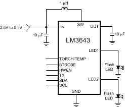
可拍照手机白色 LED 闪光灯
LM3643 是一款双 LED 闪存驱动器,能够以较小的解决方案尺寸提供高度可调节性。LM3643 采用 2MHz 或 4MHz 固定频率同步升压转换器为 1.5A 恒流 LED 源供电。LM3643 升压闪存驱动器可提供的总 LED 电流为 1.5A (ILED1 + ILED2)。 两个 128 级电流源可灵活调整 LED1 与 LED2 之间的电流比,每个驱动器最多能够提供 1.5A 电流(例如:ILED1 = 1.5A 和 ILED2 = 0FF;ILED1 = 0FF 和 ILED2 = 1.5A;或者电流低于 1.5A 的电流配置:ILED1 = 950mA,ILED2 = 250mA)。自适应调节方法可确保电流源保持可调节状态,并且最大限度地提升效率。
LM3643 的功能由兼容 I2C 的接口控制。这些 功能 包括:硬件闪光灯和硬件手电筒引脚(STROBE 和 TORCH/TEMP)、TX 中断和负温度系数 (NTC) 热敏电阻监视器。器件在每个输出引脚均提供了可独立编程的电流,以便在闪存模式或录像(手电筒)模式条件下驱动 LED。
该器件的开关频率选项为 2MHz 或 4MHz,具备过压保护 (OVP) 和可调节限流功能,因此可采用微型超薄电感和 10μF 陶瓷电容。该器件的工作环境温度范围为 -40°C 至 +85°C。
器件型号 | 封装 | 封装尺寸(最大值) |
---|---|---|
LM3643 | 芯片级球状引脚栅格阵列 (DSBGA) (12) | 1.69mm x 1.31mm |
ORDERING PART NUMBER | I2C ADDRESS |
---|---|
LM3643YFFR | 0x63 |
LM3643AYFFR | 0x67 |
PIN | DESCRIPTION | |
---|---|---|
NUMBER | NAME | |
A1 | GND | Input voltage connection. Connect IN to the input supply and bypass to GND with a 10-µF or larger ceramic capacitor. |
A2 | IN | Serial data input/output in the I2C Mode on LM3643. |
A3 | SDA | Drain Connection for Internal NMOS and Synchronous PMOS Switches. |
B1 | SW | Active high hardware flash enable. Drive STROBE high to turn on Flash pulse. Internal pulldown resistor of 300 kΩ between STROBE and GND. |
B2 | STROBE | Serial clock input for LM3643. |
B3 | SCL | Step-up DC-DC converter output. Connect a 10-µF ceramic capacitor between this terminal and GND. |
C1 | OUT | Active high enable pin. High = Standby, Low = Shutdown/Reset. Internal pulldown resistor of 300 kΩ between HWEN and GND. |
C2 | HWEN | Torch terminal input or threshold detector for NTC temperature sensing and current scale back. |
C3 | TORCH/TEMP | High-side current source output for flash LED. |
D1 | LED2 | Configurable dual polarity power amplifier synchronization input. Internal pulldown resistor of 300 kΩ between TX and GND. |
D2 | TX | High-side current source output for flash LED. |
D3 | LED1 |
MIN | MAX | UNIT | ||
---|---|---|---|---|
IN, SW, OUT, LED1, LED2 | −0.3 | 6 | V | |
SDA, SCL, TX, TORCH/TEMP, HWEN, STROBE | −0.3 to the lesser of (VIN+0.3) w/ 6 V max | V | ||
Continuous power dissipation(3) | Internally limited | |||
Junction temperature (TJ-MAX) | 150 | °C | ||
Maximum lead temperature (soldering) | See(4) | |||
Storage temperature, Tstg | −65 | 150 | °C |
VALUE | UNIT | |||
---|---|---|---|---|
V(ESD) | Electrostatic discharge | Human-body model (HBM), per ANSI/ESDA/JEDEC JS-001(1) | ±2500 | V |
Charged-device model (CDM), per JEDEC specification JESD22-C101(2) | ±1500 |
MIN | MAX | UNIT | ||
---|---|---|---|---|
VIN | 2.5 | 5.5 | V | |
Junction temperature (TJ) | −40 | 125 | °C | |
Ambient temperature (TA)(3) | −40 | 85 |
THERMAL METRIC(1) | LM3643 | UNIT | |
---|---|---|---|
DSBGA | |||
12 PINS | |||
RθJA | Junction-to-ambient thermal resistance | 90.2 | °C/W |
RθJC(top) | Junction-to-case (top) thermal resistance | 0.5 | |
RθJB | Junction-to-board thermal resistance | 40.0 | |
ψJT | Junction-to-top characterization parameter | 3.0 | |
ψJB | Junction-to-board characterization parameter | 39.2 |
PARAMETER | TEST CONDITIONS | MIN | TYP | MAX | UNIT | ||
---|---|---|---|---|---|---|---|
CURRENT SOURCE SPECIFICATIONS | |||||||
ILED1/2 | Current source accuracy | VOUT = 4 V, flash code = 0x7F = 1.5 A flash | –7% | 1.5 | 7% | A | |
VOUT = 4 V, torch code = 0x3F = 89.3 mA torch or | –10% | 89.3 | 10% | mA | |||
VHR | LED1 and LED2 current source regulation voltage | ILED1/2 = 729 mA | Flash | 290 | mV | ||
ILED1/2 = 179 mA | Torch | 158 | |||||
VOVP | ON threshold | 4.86 | 5 | 5.1 | V | ||
OFF threshold | 4.75 | 4.88 | 4.99 | ||||
STEP-UP DC/DC CONVERTER SPECIFICATIONS | |||||||
RPMOS | PMOS switch on-resistance | 86 | mΩ | ||||
RNMOS | NMOS switch on-resistance | 65 | mΩ | ||||
ICL | Switch current limit | Reg 0x07, bit[0] = 0 | –12% | 1.9 | 12% | A | |
Reg 0x07, bit[0] = 1 | –12% | 2.8 | 12% | ||||
UVLO | Undervoltage lockout threshold | Falling VIN | –2% | 2.5 | 2% | V | |
VTRIP | NTC comparator trip threshold | Reg 0x09, bits[3:1] = '100' | –5% | 0.6 | 5% | V | |
INTC | NTC current | –6% | 50 | 6% | µA | ||
VIVFM | Input voltage flash monitor trip threshold | Reg 0x02, bits[5:3] = '000' | –3% | 2.9 | 3% | V | |
IQ | Quiescent supply current | Device not switching pass mode | 0.3 | 0.75 | mA | ||
ISD | Shutdown supply current | Device disabled, HWEN = 0 V 2.5 V ≤ VIN ≤ 5.5 V |
0.1 | 4 | µA | ||
ISB | Standby supply current | Device disabled, HWEN = 1.8 V 2.5 V ≤ VIN ≤ 5.5 V |
2.5 | 10 | µA | ||
HWEN, TORCH/TEMP, STROBE, TX VOLTAGE SPECIFICATIONS | |||||||
VIL | Input logic low | 2.5 V ≤ VIN ≤ 5.5 V | 0 | 0.4 | V | ||
VIH | Input logic high | 1.2 | VIN | V | |||
I2C-COMPATIBLE INTERFACE SPECIFICATIONS (SCL, SDA) | |||||||
VIL | Input logic low | 2.5 V ≤ VIN ≤ 4.2 V | 0 | 0.4 | V | ||
VIH | Input logic high | 1.2 | VIN | V | |||
VOL | Output logic low | ILOAD = 3 mA | 400 | mV |
MIN | NOM | MAX | UNIT | ||
---|---|---|---|---|---|
t1 | SCL clock period | 2.4 | µs | ||
t2 | Data in set-up time to SCL high | 100 | ns | ||
t3 | Data out stable After SCL low | 0 | ns | ||
t4 | SDA low set-up time to SCL Low (start) | 100 | ns | ||
t5 | SDA high hold time after SCL high (stop) | 100 | ns |
PARAMETER | TEST CONDITIONS | MIN | TYP | MAX | UNIT | |
---|---|---|---|---|---|---|
ƒSW | Switching frequency | 2.5 V ≤ VIN ≤ 5.5 V | –6% | 4 | 6% | MHz |
ILED = 1.5 A | ƒSW = 2 MHz | Flash |
ILED = 1 A | ƒSW = 2 MHz | Flash |
ILED = 179 mA | ƒSW = 2 MHz | Torch |
HWEN = VIN | I2C = VIN | |
HWEN = 1.8 V | I2C = 1.8 V | |
ILED = 1.5 A | ƒSW = 4 MHz | VLED = 4.5 V |
ICL = 1.9 A |
ILED = 1.5 A | ƒSW = 4 MHz | VLED = 4.5 V |
ICL = 2.8 A |
ILED = 1.5 A | ƒSW = 4 MHz | Flash |
ILED = 730 mA | ƒSW = 2 MHz | Flash |
ILED = 179 mA | ƒSW = 4 MHz | Torch |
HWEN = 0 V | I2C = 0 V | |
HWEN = 1.8 V | I2C = 0 V | |
ILED = 1.5 A | ƒSW = 2 MHz | VLED = 4.5 V |
ICL = 1.9 A |
ILED = 1.5 A | ƒSW = 2 MHz | VLED = 4.5 V |
ICL = 2.8 A |
The LM3643 is a high-power white LED flash driver capable of delivering up to 1.5 A in either of the two parallel LEDs. The total allowed LED current during operation of the LM3643 (ILED1 + ILED2) is 1.5 A. The device incorporates a 2-MHz or 4-MHz constant frequency-synchronous current-mode PWM boost converter and dual high-side current sources to regulate the LED current over the 2.5-V to 5.5-V input voltage range.
The LM3643 PWM DC-DC boost converter switches and boosts the output to maintain at least VHR across each of the current sources (LED1/2). This minimum headroom voltage ensures that both current sources remain in regulation. If the input voltage is above the LED voltage + current source headroom voltage the device does not switch, but turns the PFET on continuously (Pass mode). In Pass mode the difference between (VIN − ILED × RPMOS) and the voltage across the LED is dropped across the current source.
The LM3643 has three logic inputs including a hardware Flash Enable (STROBE), a hardware Torch Enable (TORCH/TEMP, TORCH = default), and a Flash Interrupt input (TX) designed to interrupt the flash pulse during high battery-current conditions. These logic inputs have internal 300-kΩ (typical) pulldown resistors to GND.
Additional features of the LM3643 include an internal comparator for LED thermal sensing via an external NTC thermistor and an input voltage monitor that can reduce the Flash current during low VIN conditions. It also has a Hardware Enable (HWEN) pin that can be used to reset the state of the device and the registers by pulling the HWEN pin to ground.
Control is done via an I2C-compatible interface. This includes adjustment of the Flash and Torch current levels, changing the Flash Timeout Duration, and changing the switch current limit. Additionally, there are flag and status bits that indicate flash current time-out, LED overtemperature condition, LED failure (open/short), device thermal shutdown, TX interrupt, and VIN undervoltage conditions.
In Flash Mode, the LED current sources (LED1/2) provide 128 target current levels from 10.9 mA to 1500 mA. The total allowed LED current during operation is 1.5 A (ILED1 + ILED2 = 1.5 A). Once the Flash sequence is activated the current source (LED) ramps up to the programmed Flash current by stepping through all current steps until the programmed current is reached. The headroom in the two current sources can be regulated to provide 10.9 mA to 1.5 A on each of the two output legs. There is an option in the register settings to keep the two currents in the output leg the same.
When the device is enabled in Flash Mode through the Enable Register, all mode bits in the Enable Register are cleared after a flash time-out event.
In Torch mode, the LED current sources (LED1/2) provide 128 target current levels from 0.977 mA to 179 mA . The Torch currents are adjusted via the LED1 and LED2 LED Torch Brightness Registers. Torch mode is activated by the Enable Register (setting M1, M0 to '10'), or by pulling the TORCH/TEMP pin HIGH when the pin is enabled (Enable Register) and set to Torch Mode. Once the TORCH sequence is activated the active current sources (LED1/2) ramps up to the programmed Torch current by stepping through all current steps until the programmed current is reached. The rate at which the current ramps is determined by the value chosen in the Timing Register.
Torch Mode is not affected by Flash Timeout or by a TX Interrupt event.
In IR Mode, the target LED current is equal to the value stored in the LED1/2 Flash Brightness Registers. When IR mode is enabled (setting M1, M0 to '01'), the boost converter turns on and set the output equal to the input (pass-mode). At this point, toggling the STROBE pin enables and disables the LED1/2 current sources (if enabled). The strobe pin can only be set to be Level sensitive, meaning all timing of the IR pulse is externally controlled. In IR Mode, the current sources do not ramp the LED outputs to the target. The current transitions immediately from off to on and then on to off.
Turn on of the LM3643 Torch and Flash modes can be done through the Enable Register. On start-up, when VOUT is less than VIN the internal synchronous PFET turns on as a current source and delivers 200 mA (typical) to the output capacitor. During this time the current source (LED) is off. When the voltage across the output capacitor reaches 2.2 V (typical) the current source turns on. At turnon the current source steps through each FLASH or TORCH level until the target LED current is reached. This gives the device a controlled turnon and limits inrush current from the VIN supply.
The LM3643 starts up in Pass Mode and stays there until Boost Mode is needed to maintain regulation. If the voltage difference between VOUT and VLED falls below VHR, the device switches to Boost Mode. In Pass Mode the boost converter does not switch, and the synchronous PFET turns fully on bringing VOUT up to VIN − ILED × RPMOS. In Pass Mode the inductor current is not limited by the peak current limit.
The TX pin is a Power Amplifier Synchronization input. This is designed to reduce the flash LED current and thus limit the battery current during high battery current conditions such as PA transmit events. When the LM3643 is engaged in a Flash event, and the TX pin is pulled high, the LED current is forced into Torch Mode at the programmed Torch current setting. If the TX pin is then pulled low before the Flash pulse terminates, the LED current returns to the previous Flash current level. At the end of the Flash time-out, whether the TX pin is high or low, the LED current turns off.
The LM3643 has the ability to adjust the flash current based upon the voltage level present at the IN pin utilizing the Input Voltage Flash Monitor (IVFM). The adjustable threshold IVFM-D ranges from 2.9 V to 3.6 V in 100-mV steps, with three different usage modes (Stop and Hold, Adjust Down Only, Adjust Up and Down). The Flags2 Register has the IVFM flag bit set when the input voltage crosses the IVFM-D value. Additionally, the IVFM-D threshold sets the input voltage boundary that forces the LM3643 to either stop ramping the flash current during start-up (Stop and Hold Mode) or to start decreasing the LED current during the flash (Down Adjust Only and Up and Down Adjust). In Adjust Up and Down mode, the IVFM-D value plus the hysteresis voltage threshold set the input voltage boundary that forces the LM3643 to start ramping the flash current back up towards the target.
If the LM3643 enters a fault condition, the device sets the appropriate flag in the Flags1 and Flags2 Registers (0x0A and 0x0B), and place the device into standby by clearing the Mode Bits ([1],[0]) in the Enable Register. The LM3643 remains in standby until an I2C read of the Flags1 and Flags2 Registers are completed. Upon clearing the flags/faults, the device can be restarted (Flash, Torch, IR, etc.). If the fault is still present, the LM3643 re-enters the fault state and enters standby again.
The Flash Time-Out period sets the amount of time that the Flash Current is being sourced from the current sources (LED1/2). The LM3643 has 16 timeout levels ranging from 10 ms to 400 ms (see Timing Configuration Register (0x08) for more detail).
The output voltage is limited to typically 5 V (see VOVP spec in the Electrical Characteristics). In situations such as an open LED, the LM3643 raises the output voltage in order to try and keep the LED current at its target value. When VOUT reaches 5 V (typical) the overvoltage comparator trips and turns off the internal NFET. When VOUT falls below the “VOVP Off Threshold”, the LM3643 begins switching again. The mode bits are cleared, and the OVP flag is set, when an OVP condition is present for three rising OVP edges. This prevents momentary OVP events from forcing the device to shut down.
The LM3643 features two selectable inductor current limits that are programmable through the I2C-compatible interface. When the inductor current limit is reached, the LM3643 terminates the charging phase of the switching cycle. Switching resumes at the start of the next switching period. If the overcurrent condition persists, the device operates continuously in current limit.
Since the current limit is sensed in the NMOS switch, there is no mechanism to limit the current when the device operates in Pass Mode (current does not flow through the NMOS in pass mode). In Boost mode or Pass mode if VOUT falls below 2.3 V, the device stops switching, and the PFET operates as a current source limiting the current to 200 mA. This prevents damage to the LM3643 and excessive current draw from the battery during output short-circuit conditions. The mode bits are not cleared upon a Current Limit event, but a flag is set.
The TORCH/TEMP pin, when set to TEMP mode, serves as a threshold detector and bias source for negative temperature coefficient (NTC) thermistors. When the voltage at TEMP goes below the programmed threshold, the LM3643 is placed into standby mode. The NTC threshold voltage is adjustable from 200 mV to 900 mV in 100-mV steps. The NTC bias current is set to 50 µA. The NTC detection circuitry can be enabled or disabled via the Enable Register. If enabled, the NTC block turns on and off during the start and stop of a Flash/Torch event.
Additionally, the NTC input looks for an open NTC connection and a shorted NTC connection. If the NTC input falls below 100 mV, the NTC short flag is set, and the device is disabled. If the NTC input rises above 2.3 V, the NTC Open flag is set, and the device is disabled. These fault detections can be individually disabled/enabled via the NTC Open Fault Enable bit and the NTC Short Fault Enable bit.
The LM3643 has an internal comparator that monitors the voltage at IN and forces the LM3643 into standby if the input voltage drops to 2.5 V. If the UVLO monitor threshold is tripped, the UVLO flag bit is set in the Flags1 Register (0x0A). If the input voltage rises above 2.5 V, the LM3643 is not available for operation until there is an I2C read of the Flags1 Register (0x0A). Upon a read, the Flags1 register is cleared, and normal operation can resume if the input voltage is greater than 2.5 V.
When the LM3643 die temperature reaches 150°C, the thermal shutdown detection circuit trips, forcing the LM3643 into standby and writing a '1' to the corresponding bit of the Flags1 Register (0x0A) (Thermal Shutdown bit). The LM3643 is only allowed to restart after the Flags1 Register (0x0A) is read, clearing the fault flag. Upon restart, if the die temperature is still above 150°C, the LM3643 resets the Fault flag and re-enters standby.
The LED Fault flags read back a '1' if the device is active in Flash or Torch mode and either active LED output experiences a short condition. The Output Short Fault flag reads back a '1' if the device is active in Flash or Torch mode and the boost output experiences a short condition. An LED short condition is determined if the voltage at LED1 or LED2 goes below 500 mV (typ.) while the device is in Torch or Flash mode. There is a deglitch time of 256 μs before the LED Short flag is valid and a deglitch time of 2.048 ms before the VOUT Short flag is valid. The LED Short Faults can be reset to '0' by removing power to the LM3643, setting HWEN to '0', setting the SW RESET bit to a '1', or by reading back the Flags1 Register (0x0A on LM3643). The mode bits are cleared upon an LED and/or VOUT short fault.
MODE1 | MODE0 | STROBE EN | TORCH EN | STROBE PIN | TORCH PIN | ACTION |
---|---|---|---|---|---|---|
0 | 0 | 0 | 0 | X | X | Standby |
0 | 0 | 0 | 1 | X | pos edge | Ext Torch |
0 | 0 | 1 | 0 | pos edge | X | Ext Flash |
0 | 0 | 1 | 1 | 0 | pos edge | Standalone Torch |
0 | 0 | 1 | 1 | pos edge | 0 | Standalone Flash |
0 | 0 | 1 | 1 | pos edge | pos edge | Standalone Flash |
1 | 0 | X | X | X | X | Int Torch |
1 | 1 | X | X | X | X | Int Flash |
0 | 1 | 0 | X | X | X | IRLED Standby |
0 | 1 | 1 | X | 0 | X | IRLED Standby |
0 | 1 | 1 | X | pos edge | X | IRLED enabled |
The data on SDA must be stable during the HIGH period of the clock signal (SCL). In other words, the state of the data line can only be changed when SCL is LOW.
A pullup resistor between the controller's VIO line and SDA must be greater than [(VIO - VOL) / 3 mA] to meet the VOL requirement on SDA. Using a larger pullup resistor results in lower switching current with slower edges, while using a smaller pullup results in higher switching currents with faster edges.
START and STOP conditions classify the beginning and the end of the I2C session. A START condition is defined as the SDA signal transitioning from HIGH to LOW while SCL line is HIGH. A STOP condition is defined as the SDA transitioning from LOW to HIGH while SCL is HIGH. The I2C master always generates START and STOP conditions. The I2C bus is considered busy after a START condition and free after a STOP condition. During data transmission, the I2C master can generate repeated START conditions. First START and repeated START conditions are equivalent, function-wise.
Every byte put on the SDA line must be eight bits long, with the most significant bit (MSB) transferred first. Each byte of data has to be followed by an acknowledge bit. The acknowledge related clock pulse is generated by the master. The master releases the SDA line (HIGH) during the acknowledge clock pulse. The LM3643 pulls down the SDA line during the 9th clock pulse, signifying an acknowledge. The LM3643 generates an acknowledge after each byte is received. There is no acknowledge created after data is read from the device.
After the START condition, the I2C master sends a chip address. This address is seven bits long followed by an eighth bit which is a data direction bit (R/W). The LM3643 7-bit address is 0x63. The device address for the LM3643A is 0x67. For the eighth bit, a '0' indicates a WRITE and a '1' indicates a READ. The second byte selects the register to which the data is written. The third byte contains data to write to the selected register.
The device address for the LM3643 is 1100011 (0x63). The device address for the LM3643A is 1100111 (0x67). After the START condition, the I2C-compatible master sends the 7-bit address followed by an eighth read or write bit (R/W). R/W = 0 indicates a WRITE and R/W = 1 indicates a READ. The second byte following the device address selects the register address to which the data is written. The third byte contains the data for the selected register.
Bit 7 | Bit 6 | Bit 5 | Bit 4 | Bit 3 | Bit 2 | Bit 1 | Bit 0 |
---|---|---|---|---|---|---|---|
TX Pin Enable
0 = Disabled 1 = Enabled (Default ) |
Strobe Type
0 = Level Triggered (Default) 1 = Edge Triggered |
Strobe Enable
0 = Disabled (Default ) 1 = Enabled |
TORCH/TEMP Pin Enable
0 = Disabled (Default ) 1 = Enabled |
Mode Bits: M1, M0
00 = Standby (Default) 01 = IR Drive 10 = Torch 11 = Flash |
LED2 Enable
0 = OFF (Default ) 1 = ON |
LED1 Enable
0 = OFF (Default) 1 = ON |
NOTE
Edge Strobe Mode is not valid in IR MODE. Switching between Level and Edge Strobe Types while the device is enabled is not recommended.
In Edge or Level Strobe Mode, it is recommended that the trigger pulse width be set greater than 1 ms to ensure proper turn-on of the device.
Bit 7 | Bit 6 | Bit 5 | Bit 4 | Bit 3 | Bit 2 | Bit 1 | Bit 0 |
---|---|---|---|---|---|---|---|
RFU | UVLO Circuitry (Default)
0 = Disabled (Default) 1 = Enabled |
IVFM Levels
000 = 2.9 V (Default) 001 = 3 V 010 = 3.1 V 011 = 3.2 V 100 = 3.3 V 101 = 3.4 V 110 = 3.5 V 111 = 3.6 V |
IVFM Hysteresis
0 = 0 mV (Default) 1 = 50 mV |
IVFM Selection
00 = Disabled 01 = Stop and Hold Mode (Default) 10 = Down Mode 11 = Up and Down Mode |
NOTE
IVFM Mode Bits are static once the LM3643 is enabled in Torch, Flash or IR modes. If the IVFM mode needs to be updated, disable the device and then change the mode bits to the desired state.
Bit 7 | Bit 6 | Bit 5 | Bit 4 | Bit 3 | Bit 2 | Bit 1 | Bit 0 |
---|---|---|---|---|---|---|---|
LED2 Flash Current Override
0 = LED2 Flash Current is not set to LED1 Flash Current 1 = LED2 Flash Current is set to LED1 Flash Current (Default) |
LED1 Flash Brightness Level
IFLASH1/2 (mA) ≈ (Brightness Code × 11.725 mA) + 10.9 mA 0000000 = 10.9 mA ....................... 0111111 = 729 mA (Default) ....................... 1111111 = 1.5 A |
Bit 7 | Bit 6 | Bit 5 | Bit 4 | Bit 3 | Bit 2 | Bit 1 | Bit 0 |
---|---|---|---|---|---|---|---|
RFU | LED2 Flash Brightness Levels
IFLASH1/2 (mA) ≈ (Brightness Code × 11.725 mA) + 10.9 mA 0000000 = 10.9 mA ....................... 0111111 = 729 mA (Default) ....................... 1111111 = 1.5 A |
Bit 7 | Bit 6 | Bit 5 | Bit 4 | Bit 3 | Bit 2 | Bit 1 | Bit 0 |
---|---|---|---|---|---|---|---|
LED2 Torch Current Override
0 = LED2 Torch Current is not set to LED1 Torch Current 1 = LED2 Torch Current is set to LED1 Torch Current (Default) |
LED1 Torch Brightness Levels
ITORCH1/2 (mA) ≈ (Brightness Code × 1.4 mA) + 0.977 mA 0000000 = 0.977 mA ....................... 0111111 = 89.3 mA (Default) ....................... 1111111 = 179 mA |
Bit 7 | Bit 6 | Bit 5 | Bit 4 | Bit 3 | Bit 2 | Bit 1 | Bit 0 |
---|---|---|---|---|---|---|---|
RFU | LED2 Torch Brightness Levels
ITORCH1/2 (mA) ≈ (Brightness Code × 1.4 mA) + 0.977 mA 0000000 = 0.977 mA ....................... 0111111 = 89.3 mA (Default) ....................... 1111111 = 179 mA |
Bit 7 | Bit 6 | Bit 5 | Bit 4 | Bit 3 | Bit 2 | Bit 1 | Bit 0 |
---|---|---|---|---|---|---|---|
Software Reset Bit
0 = Not Reset (Default) 1 = Reset |
RFU | RFU | RFU | LED Pin Short Fault Detect
0 = Disabled 1 = Enabled (Default) |
Boost Mode
0 = Normal (Default) 1 = Pass Mode Only |
Boost Frequency Select
0 = 2 MHz (Default) 1 = 4 MHz |
Boost Current Limit Setting
0 = 1.9 A 1 = 2.8 A (Default) |
Bit 7 | Bit 6 | Bit 5 | Bit 4 | Bit 3 | Bit 2 | Bit 1 | Bit 0 |
---|---|---|---|---|---|---|---|
RFU | Torch Current Ramp Time
000 = No Ramp 001 = 1 ms (Default) 010 = 32 ms 011 = 64 ms 100 = 128 ms 101 = 256 ms 110 = 512 ms 111 = 1024 ms |
Flash Time-Out Duration
0000 = 10 ms 0001 = 20 ms 0010 = 30 ms 0011 = 40 ms 0100 = 50 ms 0101 = 60 ms 0110 = 70 ms 0111 = 80 ms 1000 = 90 ms 1001 = 100 ms 1010 = 150 ms (Default) 1011 = 200 ms 1100 = 250 ms 1101 = 300 ms 1110 = 350 ms 1111 = 400 ms |
Bit 7 | Bit 6 | Bit 5 | Bit 4 | Bit 3 | Bit 2 | Bit 1 | Bit 0 |
---|---|---|---|---|---|---|---|
RFU | TORCH Polarity
0 = Active High (Default) (Pulldown Resistor Enabled) 1 = Active Low (Pulldown Resistor Disabled) |
NTC Open Fault Enable
0 = Disabled (Default) 1 =Enable |
NTC Short Fault Enable
0 = Disabled (Default) 1 =Enable |
TEMP Detect Voltage Threshold
000 = 0.2 V 001 = 0.3 V 010 = 0.4 V 011 = 0.5 V 100 = 0.6 V (Default) 101 = 0.7 V 110 = 0.8 V 111 = 0.9 V |
TORCH/TEMP
Function Select 0 = TORCH (Default) 1 = TEMP |
NOTE
The Torch Polarity bit is static once the LM3643 is enabled in Torch, Flash or IR modes. If the Torch Polarity bit needs to be updated, disable the device and then change the Torch Polarity bit to the desired state.
Bit 7 | Bit 6 | Bit 5 | Bit 4 | Bit 3 | Bit 2 | Bit 1 | Bit 0 |
---|---|---|---|---|---|---|---|
TX Flag | VOUT Short Fault | VLED1 Short Fault | VLED2 Short Fault | Current Limit Flag | Thermal Shutdown (TSD) Fault | UVLO Fault | Flash Time-Out Flag |
Bit 7 | Bit 6 | Bit 5 | Bit 4 | Bit 3 | Bit 2 | Bit 1 | Bit 0 |
---|---|---|---|---|---|---|---|
RFU | RFU | RFU | NTC Short Fault | NTC Open Fault | IVFM Trip Flag | OVP Fault | TEMP Trip Fault |
Bit 7 | Bit 6 | Bit 5 | Bit 4 | Bit 3 | Bit 2 | Bit 1 | Bit 0 |
---|---|---|---|---|---|---|---|
RFU | The value stored is always the last current value the IVFM detection block set. ILED = IFLASH – TARGET × ((Code + 1) / 128) |
NOTE
Information in the following applications sections is not part of the TI component specification, and TI does not warrant its accuracy or completeness. TI’s customers are responsible for determining suitability of components for their purposes. Customers should validate and test their design implementation to confirm system functionality.
The LM3643 can drive two flash LEDs at currents up to 1.5 A per LED. The total LED current the LM3643 boost can deliver is 1.5 A (ILED1 + ILED2 ). The 2-MHz/4-MHz DC-DC boost regulator allows for the use of small value discrete external components.
Example requirements based on default register values:
DESIGN PARAMETER | EXAMPLE VALUE |
---|---|
Input voltage range | 2.5 V to 5.5 V |
Brightness control | I2C Register |
LED configuration | 2 parallel flash LEDs |
Boost switching frequency | 2 MHz (4 MHz selectable) |
Flash brightness | 750 mA per LED |
The LM3643 is designed to operate with a 10-µF ceramic output capacitor. When the boost converter is running, the output capacitor supplies the load current during the boost converter on-time. When the NMOS switch turns off, the inductor energy is discharged through the internal PMOS switch, supplying power to the load and restoring charge to the output capacitor. This causes a sag in the output voltage during the on-time and a rise in the output voltage during the off-time. The output capacitor is therefore chosen to limit the output ripple to an acceptable level depending on load current and input/output voltage differentials and also to ensure the converter remains stable.
Larger capacitors such as a 22-µF or capacitors in parallel can be used if lower output voltage ripple is desired. To estimate the output voltage ripple considering the ripple due to capacitor discharge (ΔVQ) and the ripple due to the capacitors ESR (ΔVESR) use the following equations:
For continuous conduction mode, the output voltage ripple due to the capacitor discharge is:
The output voltage ripple due to the output capacitors ESR is found by:
In ceramic capacitors the ESR is very low so the assumption is that 80% of the output voltage ripple is due to capacitor discharge and 20% from ESR. Table 1 lists different manufacturers for various output capacitors and their case sizes suitable for use with the LM3643.
Choosing the correct size and type of input capacitor helps minimize the voltage ripple caused by the switching of the LM3643 boost converter and reduce noise on the boost converter's input pin that can feed through and disrupt internal analog signals. In the typical application circuit a 10-µF ceramic input capacitor works well. It is important to place the input capacitor as close as possible to the LM3643 input (IN) pin. This reduces the series resistance and inductance that can inject noise into the device due to the input switching currents. Table 1 lists various input capacitors recommended for use with the LM3643.
MANUFACTURER | PART NUMBER | VALUE | CASE SIZE | VOLTAGE RATING |
---|---|---|---|---|
TDK Corporation | C1608JB0J106M | 10 µF | 0603 (1.6 mm × 0.8 mm × 0.8 mm) | 6.3 V |
TDK Corporation | C2012JB1A106M | 10 µF | 0805 (2.0 mm × 1.25 mm × 1.25 mm) | 10 V |
Murata | GRM188R60J106M | 10 µF | 0603 (1.6 mm x 0.8 mm x 0.8 mm) | 6.3 V |
Murata | GRM21BR61A106KE19 | 10 µF | 0805 (2.0 mm × 1.25 mm × 1.25 mm) | 10 V |
The LM3643 is designed to use a 0.47-µH or 1-µH inductor. Table 2 lists various inductors and their manufacturers that work well with the LM3643. When the device is boosting (VOUT > VIN) the inductor is typically the largest area of efficiency loss in the circuit. Therefore, choosing an inductor with the lowest possible series resistance is important. Additionally, the saturation rating of the inductor should be greater than the maximum operating peak current of the LM3643. This prevents excess efficiency loss that can occur with inductors that operate in saturation. For proper inductor operation and circuit performance, ensure that the inductor saturation and the peak current limit setting of the LM3643 are greater than IPEAK in the following calculation:
where
Efficiency details can be found in the Application Curves.
MANUFACTURER | L | PART NUMBER | DIMENSIONS (L×W×H) | ISAT | RDC |
---|---|---|---|---|---|
TOKO | 0.47 µH | DFE201610P-R470M | 2.0 mm x 1.6 mm x 1.0 mm | 4.1 A | 32 mΩ |
TOKO | 1 µH | DFE201610P-1R0M | 2.0 mm x 1.6 mm x 1.0 mm | 3.7 A | 58 mΩ |
ILED = 1.5 A | ƒSW = 2 MHz | Flash |
VLED = 3.55 V |
ILED = 1.5 A | ƒSW = 2 MHz | Flash |
ILED = 1.5 A | ƒSW = 4 MHz | Flash |
VLED = 3.55 V |
ILED = 1 A | ƒSW = 2 MHz | Flash |
VLED = 3.32 V |
ILED1 and LED2 = 729 mA | Flash | |
VLED = 3.18 V | ƒSW = 2 MHz |
ILED = 179 mA | ƒSW = 4 MHz | |
VLED = 2.83 V | Torch |
ILED1 and LED2 = 179 mA | ƒSW = 4 MHz | |
VLED = 2.83 V | Torch |
ILED1 = ILED2 = 730 mA | ƒSW = 2 MHz | |
VLED = 3.18 V |
ILED1 = ILED2 = 730 mA | ƒSW = 2 MHz | |
VLED = 3.18 V |
ILED1 = ILED2 = 730 mA | ƒSW = 2 MHz | |
VLED = 3.18 V | VIVFM = 3.2 V |
ILED1 = ILED2 = 730 mA | ƒSW = 2 MHz | |||
VLED = 3.18 V | VIVFM = 3.2 V |
ILED = 729 mA | ƒSW = 2 MHz | Flash |
VLED = 3.18 V |
ILED = 179 mA | Torch | |
VLED = 2.83 V | ƒSW = 2 MHz |
ILED1 and LED2 = 179 mA | ƒSW = 2 MHz | |
VLED = 2.83 V | Torch |
ILED1 = ILED2 = 730 mA | ƒSW = 2 MHz | |
VLED = 3.18 V |
ILED1 = ILED2 = 730 mA | ƒSW = 2 MHz | |
VLED = 3.18 V |
ILED1 = ILED2 = 730 mA | ƒSW = 4 MHz | |
VLED = 3.18 V |
ILED1 = ILED2 = 730 mA | ƒSW = 2 MHz | |
VLED = 3.18 V | VIVFM = 3.2 V |
The LM3643 is designed to operate from an input voltage supply range between 2.5 V and 5.5 V. This input supply must be well regulated and capable to supply the required input current. If the input supply is located far from the LM3643 additional bulk capacitance may be required in addition to the ceramic bypass capacitors.
The high switching frequency and large switching currents of the LM3643 make the choice of layout important. The following steps should be used as a reference to ensure the device is stable and maintains proper LED current regulation across its intended operating voltage and current range.
TI'S PUBLICATION OF INFORMATION REGARDING THIRD-PARTY PRODUCTS OR SERVICES DOES NOT CONSTITUTE AN ENDORSEMENT REGARDING THE SUITABILITY OF SUCH PRODUCTS OR SERVICES OR A WARRANTY, REPRESENTATION OR ENDORSEMENT OF SUCH PRODUCTS OR SERVICES, EITHER ALONE OR IN COMBINATION WITH ANY TI PRODUCT OR SERVICE.
All trademarks are the property of their respective owners.
ESD 可能会损坏该集成电路。德州仪器 (TI) 建议通过适当的预防措施处理所有集成电路。如果不遵守正确的处理措施和安装程序 , 可能会损坏集成电路。
ESD 的损坏小至导致微小的性能降级 , 大至整个器件故障。 精密的集成电路可能更容易受到损坏 , 这是因为非常细微的参数更改都可能会导致器件与其发布的规格不相符。
以下页中包括机械、封装和可订购信息。这些信息是针对指定器件可提供的最新数据。这些数据会在无通知且不对本文档进行修订的情况下发生改变。欲获得该数据表的浏览器版本,请查阅左侧的导航栏。
德州仪器(TI) 及其下属子公司有权根据 JESD46 最新标准, 对所提供的产品和服务进行更正、修改、增强、改进或其它更改, 并有权根据 JESD48最新标准中止提供任何产品和服务。客户在下订单前应获取最新的相关信息, 并验证这些信息是否完整且是最新的。所有产品的销售都遵循在订单确认时所提供的TI 销售条款与条件。
TI 保证其所销售的组件的性能符合产品销售时 TI 半导体产品销售条件与条款的适用规范。仅在 TI 保证的范围内,且 TI 认为有必要时才会使用测试或其它质量控制技术。除非适用法律做出了硬性规定,否则没有必要对每种组件的所有参数进行测试。
TI 对应用帮助或客户产品设计不承担任何义务。客户应对其使用 TI 组件的产品和应用自行负责。为尽量减小与客户产品和应用相关的风险,客户应提供充分的设计与操作安全措施。
TI 不对任何 TI 专利权、版权、屏蔽作品权或其它与使用了 TI 组件或服务的组合设备、机器或流程相关的 TI 知识产权中授予 的直接或隐含权限作出任何保证或解释。TI所发布的与第三方产品或服务有关的信息,不能构成从 TI 获得使用这些产品或服 务的许可、授权、或认可。使用此类信息可能需要获得第三方的专利权或其它知识产权方面的许可,或是 TI 的专利权或其它知识产权方面的许可。
对于 TI 的产品手册或数据表中 TI 信息的重要部分,仅在没有对内容进行任何篡改且带有相关授权、条件、限制和声明的情况 下才允许进行复制。TI 对此类篡改过的文件不承担任何责任或义务。复制第三方的信息可能需要服从额外的限制条件。
在转售 TI 组件或服务时,如果对该组件或服务参数的陈述与 TI 标明的参数相比存在差异或虚假成分,则会失去相关 TI 组件或服务的所有明示或暗示授权,且这是不正当的、欺诈性商业行为。TI 对任何此类虚假陈述均不承担任何责任或义务。
客户认可并同意,尽管任何应用相关信息或支持仍可能由 TI 提供,但他们将独力负责满足与其产品及在其应用中使用 TI 产品相关的所有法律、法规和安全相关要求。客户声明并同意,他们具备制定与实施安全措施所需的全部专业技术和知识,可预见故障的危险后果、监测故障及其后果、降低有可能造成人身伤害的故障的发生机率并采取适当的补救措施。客户将全额赔偿因 在此类安全关键应用中使用任何 TI 组件而对 TI及其代理造成的任何损失。
在某些场合中,为了推进安全相关应用有可能对 TI 组件进行特别的促销。TI 的目标是利用此类组件帮助客户设计和创立其特有的可满足适用的功能安全性标准和要求的终端产品解决方案。尽管如此,此类组件仍然服从这些条款。
TI 组件未获得用于 FDA Class III(或类似的生命攸关医疗设备)的授权许可,除非各方授权官员已经达成了专门管控此类使 用的特别协议。
只有那些 TI 特别注明属于军用等级或“增强型塑料”的 TI 组件才是设计或专门用于军事/航空应用或环境的。购买者认可并同 意,对并非指定面向军事或航空航天用途的 TI组件进行军事或航空航天方面的应用,其风险由客户单独承担,并且由客户独 力负责满足与此类使用相关的所有法律和法规要求。
TI 已明确指定符合 ISO/TS16949 要求的产品,这些产品主要用于汽车。在任何情况下,因使用非指定产品而无法达到 ISO/TS16949要求,TI不承担任何责任。
德州仪器在线技术支持社区: www.deyisupport.com
邮寄地址: 上海市浦东新区世纪大道1568 号,中建大厦32 楼邮政编码: 200122
Copyright© 2016, 德州仪器半导体技术(上海)有限公司