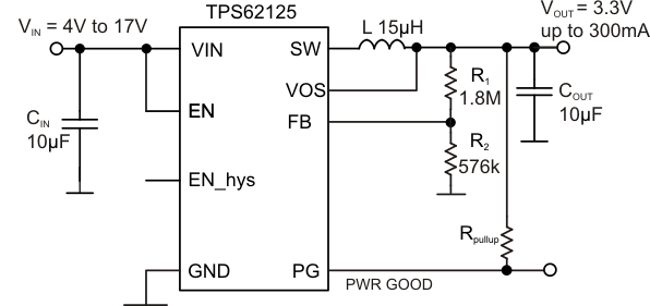
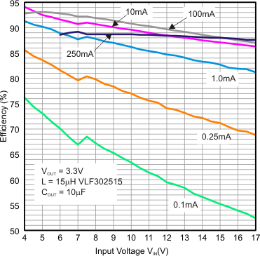
TPS62125 器件是一款高效同步降压转换器,针对低功耗/超低功耗 应用 进行了优化,输出电流高达 300mA。该器件的宽输入电压范围为 3V 至 17V,可支持由 4 节碱性电池、1 至 4 节锂离子电池串联配置以及 9V 至 15V 电压供电的 应用的输出电流传感电阻器和运算放大器而得以实现。该器件具备一个精密的低功耗使能比较器,其可用作输入电源电压监视器 (SVS),以满足系统特定的上电和断电要求。该使能比较器仅消耗 6µA 静态电流并 具备 典型值为 1.2V 的精确阈值以及可调节迟滞。借助此特性,该转换器能够从由太阳能板或者电流回路等高阻抗源供电的储能电容中提取电能,以生成电源轨。凭借其 DCS-Control 机制,该转换器可在节能模式下运行,从而在整个负载电流范围内保持最高效率。在轻载条件下,该转换器能够以脉频调制 (PFM) 模式运行并在负载电流较大时自动无缝转换至脉宽调制 (PWM) 模式。该 DCS-Control™机制已针对 PFM 模式下的低输出纹波电压进行了优化,从而最大限度地降低输出噪声 并 获得优异的交流负载稳压性能。开漏电源正常输出表示正在对输出电压进行稳压。
器件型号 | 封装 | 封装尺寸(标称值) |
---|---|---|
TPS62125 | WSON (8) | 2.00mm x 2.00mm |
PIN | I/O | DESCRIPTION | ||
---|---|---|---|---|
NAME | NO. | |||
EN | 3 | IN | Input pin for the enable comparator. Pulling this pin to GND turns the device into shutdown mode. The DC/DC converter is enabled once the rising voltage on this pin trips the enable comparator threshold, VTH EN ON of typ. 1.2 V. The DC/DC converter is turned off once a falling voltage on this pin trips the threshold, VTH EN OFF of typ. 1.15 V. The comparator threshold can be increased by connecting an external resistor to pin EN_hys. See also application section. This pin must be terminated. | |
EN_hys | 4 | OUT | Enable hysteresis open-drain output. This pin is pulled to GND when the voltage on the EN pin is below the comparator threshold VTH EN ON of typ. 1.2 V and the comparator has not yet tripped. The pin is high impedance once the enable comparator has tripped and the voltage at the pin EN is above the threshold VTH EN ON. The pin is pulled to GND once the falling voltage on the EN pin trips the threshold VTH EN OFF (1.15 V typical). This pin can be used to increase the hysteresis of the enable comparator. If not used, tie this pin to GND, or leave it open. | |
FB | 5 | IN | This is the feedback pin for the regulator. An external resistor divider network connected to this pin sets the output voltage. In case of fixed output voltage option, the resistor divider is integrated and the pin need to be connected directly to the output voltage. | |
GND | 1 | PWR | GND supply pin. | |
PG | 8 | OUT | Open drain power good output. This pin is internally pulled to GND when the device is disabled or the output voltage is below the PG threshold. The pin is floating when the output voltage is in regulation and above the PG threshold. For power good indication, the pin can be connected via a pull up resistor to a voltage rail up to 10 . The pin can sink a current up to 0.4 mA and maintain the specified high/low voltage levels. It can be used to discharge the output capacitor with up to 10 mA. In this case the current into the pin must be limited with an appropriate pull up resistor. More details can be found in the application section. If not used, leave the pin open, or connect to GND. | |
SW | 7 | OUT | This is the switch pin and is connected to the internal MOSFET switches. Connect the inductor to this pin. Do not tie this pin to VIN, VOUT or GND. | |
VIN | 2 | PWR | VIN power supply pin. | |
VOS | 6 | IN | This is the output voltage sense pin for the DCS-Control circuitry. This pin must be connected to the output voltage of the DC/DC converter. | |
Exposed Thermal PAD | – | – | This pad must be connected to GND. |
MIN | MAX | UNIT | |||
---|---|---|---|---|---|
Pin voltage(2) | VIN | –0.3 | 20 | V | |
SW (DC) | –0.3 | VIN + 0.3V | V | ||
SW (AC, less than 10ns)(3) | -3.0 | 23.5 | V | ||
EN | –0.3 | VIN + 0.3 | V | ||
FB | –0.3 | 3.6 | V | ||
VOS, PG | –0.3 | 12 | V | ||
EN_hys | –0.3 | 7 | V | ||
Power good sink current | IPG | 10 | mA | ||
EN_hys sink current | IEN_hys | 3 | mA | ||
Maximum operating junction temperature, TJ | –40 | 125 | °C | ||
Storage temperature, Tstg | –65 | 150 | °C |
VALUE | UNIT | |||
---|---|---|---|---|
V(ESD) | Electrostatic discharge | Human body model (HBM), per ANSI/ESDA/JEDEC JS-001(1) | ±2000 | V |
Charged-device model (CDM), per JEDEC specification JESD22-C101(2) | ±1000 |
MIN | NOM | MAX | UNIT | |||
---|---|---|---|---|---|---|
VIN | Supply voltage | 3 | 17 | V | ||
Output current capability | 3 V ≤ VIN < 6 V | 200 | mA | |||
6 V ≤ VIN ≤ 17 V | 300 | |||||
TA | Operating ambient temperature (1) (Unless Otherwise Noted) | –40 | 85 | °C | ||
TJ | Operating junction temperature, | –40 | 125 | °C |
THERMAL METRIC(1) | TPS62125 | UNIT | |
---|---|---|---|
DSG (WSON) | |||
8 PINS | |||
RθJA | Junction-to-ambient thermal resistance | 65.2 | °C/W |
RθJC(top) | Junction-to-case (top) thermal resistance | 93.3 | °C/W |
RθJB | Junction-to-board thermal resistance | 30.1 | °C/W |
ψJT | Junction-to-top characterization parameter | 0.5 | °C/W |
ψJB | Junction-to-board characterization parameter | 47.4 | °C/W |
RθJC(bot) | Junction-to-case (bottom) thermal resistance | 7.2 | °C/W |
PARAMETER | TEST CONDITIONS | MIN | TYP | MAX | UNIT | |
---|---|---|---|---|---|---|
SUPPLY | ||||||
VIN | Input voltage range(1) | 3 | 17 | V | ||
VOUT | Output voltage range | 1.2 | 10 | V | ||
IQ | Quiescent current | IOUT = 0 mA, device not switching, EN = VIN, regulator sleeps | 13 | 23 | µA | |
IOUT = 0 mA, device switching, VIN = 7.2 V, VOUT = 1.2 V, L = 22 µH |
14 | µA | ||||
VIN = 5 V, EN = 1.1 V, enable comparator active, device DC/DC converter off | 6 | 11 | µA | |||
IActive | Active mode current consumption | VIN = 5 V = VOUT, TA = 25°C, high-side MOSFET switch fully turned on (100% mode) | 230 | 275 | µA | |
ISD | Shutdown current(2) | Enable comparator off, EN < 0.4 V,
VOUT = SW = 0 V, VIN = 5 V |
0.35 | 2.4 | µA | |
VUVLO | Undervoltage lockout threshold | Falling VIN | 2.8 | 2.85 | V | |
Rising VIN | 2.9 | 2.95 | V | |||
ENABLE COMPARATOR THRESHOLD AND HYSTERESIS (EN, EN_hys) | ||||||
VTH EN ON | EN pin threshold rising edge | 3 V ≤ V≤ 17 V | 1.16 | 1.20 | 1.24 | V |
VTH EN OFF | EN pin threshold falling edge | 1.12 | 1.15 | 1.19 | V | |
VTH EN Hys | EN pin hysteresis IN | 50 | mV | |||
IIN EN | Input bias current into EN pin | EN = 1.3 V | 0 | 50 | nA | |
VEN_hyst | EN_hys pin output low | IEN_hyst = 1 mA, EN = 1.1 V | 0.4 | V | ||
IIN EN_hyst | Input bias current into EN_hyst pin | EN_hyst = 1.3 V | 0 | 50 | nA | |
POWER SWITCH | ||||||
RDS(ON) | High-side MOSFET ON-resistance | VIN = 3 V, I = 100 mA | 2.4 | 4 | Ω | |
VIN = 12 V, I = 100 mA | 1.5 | 2.6 | ||||
Low-side MOSFET ON-resistance | VIN = 3 V, I = 100 mA | 0.75 | 1.3 | |||
VIN = 12 V, I = 100 mA | 0.6 | 1 | ||||
ILIMF | Switch current limit high-side MOSFET | VIN = 12 V | 600 | 750 | 900 | mA |
TSD | Thermal shutdown | Increasing junction temperature | 150 | °C | ||
Thermal shutdown hysteresis | Decreasing junction temperature | 20 | °C | |||
OUTPUT | ||||||
tONmin | Minimum ON-time | VIN = 5 V, VOUT = 2.5 V | 500 | ns | ||
tOFFmin | Minimum OFF-time | VIN = 5 V | 60 | ns | ||
VREF_FB | Internal reference voltage of error amplifier | 0.808 | V | |||
VFB | Feedback voltage accuracy | Referred to internal reference (VREF_FB) | –2.5% | 0% | 2.5% | |
Feedback voltage line regulation | IOUT = 100 mA, 5 V ≤ VIN ≤ 17 V, VOUT = 3.3 V(3) | –0.05 | %/V | |||
Feedback voltage load regulation | VOUT = 3.3 V; IOUT = 1 mA to 300 mA, VIN = 12 V(3) | –0.004 | %/mA | |||
IIN_FB | Input bias current into FB pin | VFB = 0.8 V | 0 | 50 | nA | |
tStart | Regulator start-up time | Time from EN high to device starts switching, VIN = 5 V |
50 | µs | ||
tRamp | Output voltage ramp time | Time to ramp up VOUT = 1.8 V, no load | 200 | |||
ILK_SW | Leakage current into SW pin(4) | VOS = VIN = VSW = 1.8 V, EN = GND, device in shutdown mode | 1.8 | 2.85 | µA | |
IIN_VOS | Bias current into VOS pin | 0 | 50 | nA | ||
POWER GOOD OUTPUT (PG) | ||||||
VTH_PG | Power good threshold voltage | Rising VFB feedback voltage | 93% | 95% | 97% | |
Falling VFB feedback voltage | 87% | 90% | 93% | |||
VOL | PG pin output low voltage | Current into PG pin IPG= 0.4 mA | 0.3 | V | ||
VOH | PG pin output high voltage | Open drain output, external pullup resistor | 10 | V | ||
IIN_PG | Bias current into PG pin | V(PG) = 3 V, EN = 1.3 V, FB = 0.85 V | 0 | 50 | nA |
The TPS62125 high-efficiency synchronous switch mode buck converter includes TI's DCS-Control (Direct Control with Seamless Transition into Power-Save Mode), an advanced regulation topology, which combines the advantages of hysteretic and voltage mode control. Characteristics of DCS-Control are excellent AC load regulation and transient response, low-output ripple voltage and a seamless transition between PFM and PWM mode operation.
DCS-Control includes an AC loop which senses the output voltage (VOS pin) and directly feeds the information to a fast comparator stage. This comparator sets the switching frequency, which is constant for steady state operating conditions, and provides immediate response to dynamic load changes. In order to achieve accurate DC load regulation, a voltage feedback loop is used. The internally compensated regulation network achieves fast and stable operation with small external components and low ESR capacitors. The DCS-Control topology supports pulse width modulation (PWM) mode for medium and high load conditions and a power-save mode at light loads. During PWM mode, it operates in continuous conduction. The switch frequency is up to 1 MHz with a controlled frequency variation depending on the input voltage. If the load current decreases, the converter seamless enters power-save mode to maintain high efficiency down to very light loads. In power-save mode the switching frequency varies linearly with the load current. Because DCS-Control supports both operation modes within one single building block, the transition from PWM to power-save mode is seamless without effects on the output voltage. The TPS62125 offers both excellent DC voltage and superior load transient regulation, combined with very low-output voltage ripple, minimizing interference with RF circuits.
At high load currents the converter operates in quasi fixed frequency PWM mode operation and at light loads in pulse frequency modulation (PFM) mode to maintain highest efficiency over the full load current range. In PFM mode, the device generates a single switching pulse to ramp up the inductor current and recharge the output capacitor, followed by a sleep period where most of the internal circuits are shutdown to achieve a quiescent current of typically 13 µA. During this time, the load current is supported by the output capacitor. The duration of the sleep period depends on the load current and the inductor peak current.
In addition to the EN comparator, the device includes an under-voltage lockout circuit which prevents the device from misoperation at low input voltages. Both circuits are fed to an AND gate and prevents the converter from turning on the high-side MOSFET switch or low-side MOSFET under undefined conditions. The UVLO threshold is set to 2.9 V typical for rising VIN and 2.8 V typical for falling VIN. The hysteresis between rising and falling UVLO threshold ensures proper start-up. Fully functional operation is permitted for an input voltage down to the falling UVLO threshold level. The converter starts operation again once the input voltage trips the rising UVLO threshold level and the voltage at the EN pin trips VTH_EN_ON.
The EN pin is connected to an on/shutdown detector (ON/SD) and an input of the enable comparator. With a voltage level of 0.4 V or less at the EN pin, the ON/SD detector turns the device into Shutdown mode and the quiescent current is reduced to typically 350 nA. In this mode the EN comparator as well the entire internal-control circuitry are switched off. A voltage level of typical 900 mV (rising) at the EN pin triggers the on/shutdown detector and activates the internal reference VREF (typical 1.2 V), the EN comparator and the UVLO comparator. In applications with slow rising voltage levels at the EN pin, the quiescent current profile before this trip point needs to be considered, see Figure 3. Once the ON/SD detector has tripped, the quiescent current consumption of the device is typical 6 µA. The TPS62125 starts regulation once the voltage at the EN pin trips the threshold VEN_TH ON (typical 1.2 V) and the input voltage is above the UVLO threshold. It enters softstart and ramps up the output voltage. For proper operation, the EN pin must be terminated and must not be left floating. The quiescent current consumption of the TPS62125 is typical 13 µA under no load condition (not switching). See Figure 1. The DC/DC regulator stops operation once the voltage on the EN pin falls below the threshold VEN_TH OFF (typical 1.15 V) or the input voltage falls below UVLO threshold. The enable comparator features a built in hysteresis of typical 50 mV. This hysteresis can be increased with an external resistor connected to pin EN_hys.
The power good output (PG pin) is an open drain output. The circuit is active once the device is enabled. It is driven by an internal comparator connected to the FB pin voltage and an internal reference. The PG output provides a high level (open drain high impedance) once the feedback voltage exceeds typical 95% of its nominal value. The PG output is driven to low level once the FB pin voltage falls below typical 90% of its nominal value VREF_FB. The PG output goes high (high impedance) with a delay of typically 2 µs. A pull up resistor is needed to generate a high level. The PG pin can be connected via a pull up resistors to a voltage up to 10 V. This pin can also be used to discharge the output capacitor. See section Application Information for more details.
The PG output is pulled low if the voltage on the EN pin falls below the threshold VEN_TH OFF or the input voltage is below the undervoltage lockout threshold UVLO.
As soon as the junction temperature, TJ, exceeds 150°C (typical) the device goes into thermal shutdown. In this mode, the high-side and low-side MOSFETs are turned-off. The device continues its operation when the junction temperature falls below the thermal shutdown hysteresis.
The TPS62125 operates with pulse width modulation in continuous conduction mode (CCM) with a nominal switching frequency of about 1 MHz. The frequency variation in PWM mode is controlled and depends on VIN, VOUT and the inductance. The device operates in PWM mode as long the output current is higher than half the inductor's ripple current. To maintain high efficiency at light loads, the device enters power-save mode at the boundary to discontinuous conduction mode (DCM). This happens if the output current becomes smaller than half the inductor's ripple current.
With decreasing load current, the TPS62125 transitions seamlessly from PWM mode to power-save mode once the inductor current becomes discontinuous. This ensures a high efficiency at light loads. In power-save mode the converter operates in pulse frequency modulation (PFM) mode and the switching frequency decreases linearly with the load current. DCS-Control features a small and predictable output voltage ripple in power-save mode. The transition between PWM mode and power-save mode occurs seamlessly in both directions.
The minimum ON-time TONmin for a single pulse can be estimated by:
Therefore the peak inductor current in PFM mode is approximately:
where
The transition from PFM mode to PWM mode operation and back occurs at a load current of approximately 0.5 x ILPFMpeak.
The maximum switching frequency can be estimated by:
The device increases the ON-time of the high-side MOSFET switch as the input voltage comes close to the output voltage in order to keep the output voltage in regulation. This reduces the switching frequency.
With further decreasing input voltage VIN, the high-side MOSFET switch is turned on completely. In this case, the converter provides a low input-to-output voltage difference. This is particularly useful in applications with a widely variable supply voltage to achieve longest operation time by taking full advantage of the whole supply voltage span.
The minimum input voltage to maintain output voltage regulation depends on the load current and output voltage, and can be calculated as:
where
The TPS62125 has an internal soft-start circuit which controls the ramp up of the output voltage and limits the inrush current during start-up. This limits input voltage drop.
The soft-start system generates a monotonic ramp up of the output voltage and reaches an output voltage of 1.8 V typical within 240 µs after the EN pin was pulled high. For higher output voltages, the ramp up time of the output voltage can be estimated with a ramp up slew rate of about 12 mV/us. TPS62125 is able to start into a prebiased output capacitor. The converter starts with the applied bias voltage and ramps the output voltage to its nominal value. In case the output voltage is higher than the nominal value, the device starts switching once the output has been discharged by an external load or leakage current to its nominal output voltage value.
During start-up the device can provide an output current of half of the high-side MOSFET switch current limit ILIMF. Large output capacitors and high load currents may exceed the current capability of the device during start-up. In this case the start-up ramp of the output voltage will be slower.
The TPS62125 integrates a high-side MOSFET switch current limit, ILIMF, to protect the device against a short circuit. The current in the high-side MOSFET switch is monitored by a current limit comparator and once the current reaches the limit of ILIMF , the high-side MOSFET switch is turned off and the low-side MOSFET switch is turned on to ramp down the inductor current. The high-side MOSFET switch is turned on again once the zero current comparator trips and the inductor current has become zero. In this case, the output current is limited to half of the high-side MOSFET switch current limit, 0.5 x ILIMF, typ. 300mA.
NOTE
Information in the following applications sections is not part of the TI component specification, and TI does not warrant its accuracy or completeness. TI’s customers are responsible for determining suitability of components for their purposes. Customers should validate and test their design implementation to confirm system functionality.
The TPS62125 is a high-efficiency synchronous step-down converter providing a wide output voltage range from 1.2 V to 10 V.
The device operates over an input voltage range from 3 V to 17 V. The output voltage is adjustable using an external feedback divider.
The output voltage can be calculated by:
The internal reference voltage for the error amplifier, VREF_FB, is nominal 0.808 V. However for the feedback resistor divider selection, it is recommended to use the value 0.800 V as the reference. Using this value, the output voltage sets 1% higher and provides more headroom for load transients as well for line and load regulation. The current through the feedback resistors R1 and R2 should be higher than 1 µA. In applications operating over full temperature range or in noisy environments, this current may be increased for robust operation. However, higher currents through the feedback resistors impact the light load efficiency of the converter.
Table 1 shows a selection of suggested values for the feedback divider network for most common output voltages.
OUTPUT VOLTAGE | 1.2 V | 1.8 V | 3.3 V | 5 V | 6.7 V | 8 V |
---|---|---|---|---|---|---|
R1 [kΩ] | 180 | 300 | 1800 | 1100 | 1475 | 1800 |
R2 [kΩ] | 360 | 240 | 576 | 210 | 200 | 200 |
The enable comparator can be used as an adjustable input supply voltage supervisor (SVS) to start and stop the DC/DC converter depending on the input voltage level. The input voltage level, VIN_startup, at which the device starts up is set by the resistors REN1 and REN2 and can be calculated by :
The resistor values REN1 and REN2 can be calculated by:
The input voltage level VIN_stop at which the device will stop operation is set by REN1, REN2 and REN HYS and can be calculated by:
The resistor value REN_hys can be calculated according to:
The current through the resistors REN1, REN2, and REN HYS should be higher than 1 µA. In applications operating over the full temperature range and in noisy environments, the resistor values can be reduced to smaller values.
The power good open collector output needs an external pull up resistor to indicate a high level. The pull up resistor can be connected to a voltage level up to 10 V. The output can sink current up to 0.4 mA with specified output low level of less than 0.3 V. The lowest value for the pull up resistor can be calculated by:
The PG pin can be used to discharge the output capacitor. The PG output has an internal resistance RIPG of typical 600 Ω and minimum 400 Ω. The maximum sink current into the PG pin is 10 mA. In order to limit the discharge current to the maximum allowable sink current into the PG pin, the external pull up resistor RPull up can be calculated to:
In case a negative value is calculated, the external pull up resistor can be removed and the PG pin can be directly connected to the output.
The external components have to fulfill the needs of the application, but also the stability criteria of the devices control loop. The TPS62125 is optimized to work within a range of L and C combinations. The LC output filter inductance and capacitance have to be considered together, creating a double pole, responsible for the corner frequency of the converter. Table 2 can be used to simplify the output filter component selection.
INDUCTOR VALUE [µH](2) | OUTPUT CAPACITOR VALUE [µF](1) | |||
---|---|---|---|---|
10 µF | 2 x 10 µF | 22 µF | 47 µF | |
VOUT 1.2 V - 1.8 V | ||||
15 | √ | √ | √ | √ |
22 | √(3) | √ | √ | √ |
VOUT 1.8 V - 3.3 V | ||||
15 | √(3) | √ | √ | √ |
22 | √(3) | √ | √ | √ |
VOUT 3.3 V - 5 V | ||||
10 | √ | √ | √ | |
15 | √(3) | √(3) | √ | |
22 | ||||
VOUT 5 V - 10 V | ||||
10 | √(3) | √(3) | √ | |
15 | √ | √ | √ | |
22 | √ | √ | √ |
More detailed information on further LC combinations can be found in application note SLVA515.
The inductor value affects its peak-to-peak ripple current, the PWM-to-PFM transition point, the output voltage ripple and the efficiency. The selected inductor has to be rated for its DC resistance and saturation current. The inductor ripple current (ΔIL) decreases with higher inductance and increases with higher VIN or VOUT and can be estimated according to Equation 13.
Equation 14 calculates the maximum inductor current under static load conditions. The saturation current of the inductor should be rated higher than the maximum inductor current as calculated with Equation 14. This is recommended because during heavy load transient the inductor current will rise above the calculated value. A more conservative way is to select the inductor saturation current according to the high-side MOSFET switch current limit ILIMF.
where
In DC/DC converter applications, the efficiency is essentially affected by the inductor AC resistance (i.e. quality factor) and by the inductor DCR value. To achieve high-efficiency operation, take care in selecting inductors featuring a quality factor above 25 at the switching frequency. Increasing the inductor value produces lower RMS currents, but degrades transient response. For a given physical inductor size, increased inductance usually results in an inductor with lower saturation current.
The total losses of the coil consist of both the losses in the DC resistance (RDC) and the following frequency-dependent components:
The following inductor series from different suppliers have been used with the TPS62125.
INDUCTANCE [µH] | DCR [Ω] | DIMENSIONS [mm3] | INDUCTOR TYPE | SUPPLIER |
---|---|---|---|---|
10 / 15 | 0.33 max / 0.44 max. | 3.3 x 3.3 x 1.4 | LPS3314 | Coilcraft |
22 | 0.36 max. | 3.9 x 3.9 x 1.8 | LPS4018 | Coilcraft |
15 | 0.33 max. | 3.0 x 2.5 x 1.5 | VLF302515 | TDK |
10/15 | 0.44 max / 0.7 max. | 3.0 x 3.0 x 1.5 | LPS3015 | Coilcraft |
10 | 0.38 typ. | 3.2 × 2.5 × 1.7 | LQH32PN | Murata |
Ceramic capacitors with low ESR values provide the lowest output voltage ripple and are recommended. The output capacitor requires either an X7R or X5R dielectric. Y5V and Z5U dielectric capacitors, aside from their wide variation in capacitance over temperature, become resistive at high frequencies.
At light load currents the converter operates in power-save mode and the output voltage ripple is dependent on the output capacitor value and the PFM peak inductor current. Higher output capacitor values minimize the voltage ripple in PFM Mode and tighten DC output accuracy in PFM mode. In order to achieve specified regulation performance and low-output voltage ripple, the DC-bias characteristic of ceramic capacitors must be considered. The effective capacitance of ceramic capacitors drops with increasing DC-bias voltage. Due to this effect, it is recommended for output voltages above 3.3 V to use at least 1 x 22-µF or 2 x 10-µF ceramic capacitors on the output.
Because of the nature of the buck converter having a pulsating input current, a low ESR input capacitor is required for best input voltage filtering and minimizing the interference with other circuits caused by high input voltage spikes. For most applications, a 10-µF ceramic capacitor is recommended. The voltage rating and DC bias characteristic of ceramic capacitors need to be considered. The input capacitor can be increased without any limit for better input voltage filtering.
For applications powered from high impedance sources, a tantalum polymer capacitor should be used to buffer the input voltage for the TPS62125. Tantalum polymer capacitors provide a constant capacitance vs. DC bias characteristic compared to ceramic capacitors. In this case, a 10-µF ceramic capacitor should be used in parallel to the tantalum polymer capacitor to provide low ESR.
Take care when using only small ceramic input capacitors. When a ceramic capacitor is used at the input and the power is being supplied through long wires, such as from a wall adapter, a load step at the output or VIN step on the input can induce large ringing at the VIN pin. This ringing can couple to the output and be mistaken as loop instability or could even damage the part by exceeding the maximum ratings. In case the power is supplied via a connector e.g. from a wall adapter, a hot-plug event can cause voltage overshoots on the VIN pin exceeding the absolute maximum ratings and can damage the device, too. In this case a tantalum polymer capacitor or overvoltage protection circuit reduces the voltage overshoot, see Figure 45.
Table 4 shows a list of input/output capacitors.
CAPACITANCE [µF] | SIZE | CAPACITOR TYPE | USAGE | SUPPLIER |
---|---|---|---|---|
10 | 0805 | GRM21B 25V X5R | CIN /COUT | Murata |
10 | 0805 | GRM21B 16V X5R | COUT | Murata |
22 | 1206 | GRM31CR61 16V X5R | COUT | Murata |
22 | B2 (3.5x2.8x1.9) | 20TQC22MYFB | CIN / input protection | Sanyo |
.
The TPS62125 has no special requirements for its input power supply. The input power supply's output current needs to be rated according to the supply voltage, output voltage, and output current of the TPS62125.
As for all switching power supplies, the layout is an important step in the design. Proper function of the device demands careful attention to PCB layout. Take care in the board layout to get the specified performance. If the layout is not carefully done, the regulator could show frequency variations, poor line and/or load regulation, stability issues as well as EMI problems. It is critical to provide a low-inductance, low-impedance ground path. Therefore, use wide and short traces for the paths conducting AC current of the DC/DC converter. The area of the AC current loop (input capacitor – TPS62125 – inductor – output capacitor) should be routed as small as possible to avoid magnetic field radiation. Therefore the input capacitor should be placed as close as possible to the IC pins as well as the inductor and output capacitor. Use a common power GND node and a different node for the signal GND to minimize the effects of ground noise. Keep the common path to the GND pin, which returns both the small signal components and the high current of the output capacitors as short as possible to avoid ground noise. A well proven practice is to merge small signal GND and power GND path at the exposed thermal pad. The FB divider network and the FB line should be routed away from the inductor and the SW node to avoid noise coupling. The VOS line should be connected as short as possible to the output, ideally to the VOUT terminal of the inductor. Keep the area of the loop VOS node – inductor – SW node small. The exposed thermal pad must be soldered to the circuit board for mechanical reliability and to achieve appropriate power dissipation.
TI'S PUBLICATION OF INFORMATION REGARDING THIRD-PARTY PRODUCTS OR SERVICES DOES NOT CONSTITUTE AN ENDORSEMENT REGARDING THE SUITABILITY OF SUCH PRODUCTS OR SERVICES OR A WARRANTY, REPRESENTATION OR ENDORSEMENT OF SUCH PRODUCTS OR SERVICES, EITHER ALONE OR IN COMBINATION WITH ANY TI PRODUCT OR SERVICE.
要接收文档更新通知,请导航至 TI.com 上的器件产品文件夹。请单击右上角的通知我 进行注册,即可收到任意产品信息更改每周摘要。有关更改的详细信息,请查看任意已修订文档中包含的修订历史记录。
下列链接提供到 TI 社区资源的连接。链接的内容由各个分销商“按照原样”提供。这些内容并不构成 TI 技术规范,并且不一定反映 TI 的观点;请参阅 TI 的 《使用条款》。
DCS-Control, E2E are trademarks of Texas Instruments.
All other trademarks are the property of their respective owners.
这些装置包含有限的内置 ESD 保护。 存储或装卸时,应将导线一起截短或将装置放置于导电泡棉中,以防止 MOS 门极遭受静电损伤。
SLYZ022 — TI Glossary.
This glossary lists and explains terms, acronyms, and definitions.
以下页面包括机械、封装和可订购信息。这些信息是指定器件的最新可用数据。这些数据发生变化时,我们可能不会另行通知或修订此文档。如欲获取此产品说明书的浏览器版本,请参见左侧的导航栏。
德州仪器(TI) 及其下属子公司有权根据 JESD46 最新标准, 对所提供的产品和服务进行更正、修改、增强、改进或其它更改, 并有权根据 JESD48最新标准中止提供任何产品和服务。客户在下订单前应获取最新的相关信息, 并验证这些信息是否完整且是最新的。所有产品的销售都遵循在订单确认时所提供的TI 销售条款与条件。
TI 保证其所销售的组件的性能符合产品销售时 TI 半导体产品销售条件与条款的适用规范。仅在 TI 保证的范围内,且 TI 认为有必要时才会使用测试或其它质量控制技术。除非适用法律做出了硬性规定,否则没有必要对每种组件的所有参数进行测试。
TI 对应用帮助或客户产品设计不承担任何义务。客户应对其使用 TI 组件的产品和应用自行负责。为尽量减小与客户产品和应用相关的风险,客户应提供充分的设计与操作安全措施。
TI 不对任何 TI 专利权、版权、屏蔽作品权或其它与使用了 TI 组件或服务的组合设备、机器或流程相关的 TI 知识产权中授予 的直接或隐含权限作出任何保证或解释。TI所发布的与第三方产品或服务有关的信息,不能构成从 TI 获得使用这些产品或服 务的许可、授权、或认可。使用此类信息可能需要获得第三方的专利权或其它知识产权方面的许可,或是 TI 的专利权或其它知识产权方面的许可。
对于 TI 的产品手册或数据表中 TI 信息的重要部分,仅在没有对内容进行任何篡改且带有相关授权、条件、限制和声明的情况 下才允许进行复制。TI 对此类篡改过的文件不承担任何责任或义务。复制第三方的信息可能需要服从额外的限制条件。
在转售 TI 组件或服务时,如果对该组件或服务参数的陈述与 TI 标明的参数相比存在差异或虚假成分,则会失去相关 TI 组件或服务的所有明示或暗示授权,且这是不正当的、欺诈性商业行为。TI 对任何此类虚假陈述均不承担任何责任或义务。
客户认可并同意,尽管任何应用相关信息或支持仍可能由 TI 提供,但他们将独力负责满足与其产品及在其应用中使用 TI 产品相关的所有法律、法规和安全相关要求。客户声明并同意,他们具备制定与实施安全措施所需的全部专业技术和知识,可预见故障的危险后果、监测故障及其后果、降低有可能造成人身伤害的故障的发生机率并采取适当的补救措施。客户将全额赔偿因 在此类安全关键应用中使用任何 TI 组件而对 TI及其代理造成的任何损失。
在某些场合中,为了推进安全相关应用有可能对 TI 组件进行特别的促销。TI 的目标是利用此类组件帮助客户设计和创立其特有的可满足适用的功能安全性标准和要求的终端产品解决方案。尽管如此,此类组件仍然服从这些条款。
TI 组件未获得用于 FDA Class III(或类似的生命攸关医疗设备)的授权许可,除非各方授权官员已经达成了专门管控此类使 用的特别协议。
只有那些 TI 特别注明属于军用等级或“增强型塑料”的 TI 组件才是设计或专门用于军事/航空应用或环境的。购买者认可并同 意,对并非指定面向军事或航空航天用途的 TI组件进行军事或航空航天方面的应用,其风险由客户单独承担,并且由客户独 力负责满足与此类使用相关的所有法律和法规要求。
TI 已明确指定符合 ISO/TS16949 要求的产品,这些产品主要用于汽车。在任何情况下,因使用非指定产品而无法达到 ISO/TS16949要求,TI不承担任何责任。
德州仪器在线技术支持社区: www.deyisupport.com
邮寄地址: 上海市浦东新区世纪大道1568 号,中建大厦32 楼邮政编码: 200122
Copyright© 2016, 德州仪器半导体技术(上海)有限公司