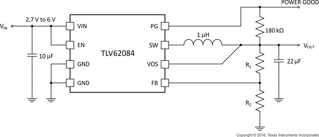
TLV6208x 系列器件是小型降压转换器,所用外部组件较少,可实现具有成本效益的解决方案。此类器件属于同步降压转换器,其输入电压范围为 2.5V/2.7V(TLV62080 为 2.5V,TLV62084x 为 2.7V)至 6V。TLV6208x 器件专注于在宽输出电流范围内实现高效降压转换。该转换器在中等至高负载条件下采用脉宽调制 (PWM) 模式,而在轻载电流条件下自动进入省电模式,从而在整个负载电流范围内保持高效运行。
为了满足系统电源轨需求,内部补偿电路支持在较大外部输出电容值范围内进行选择。凭借 DCS-Control™(无缝过渡至节能模式的直接控制)架构,该器件实现了优异的负载瞬态性能和输出电压稳压精度。该器件采用带有散热焊盘的 2mm x 2mm 晶圆级小外形无引线 (WSON) 封装。
器件型号 | 封装 | 封装尺寸(标称值) |
---|---|---|
TLV62080 | WSON (8) | 2.00mm x 2.00mm |
TLV62084, TLV62084A |
空白
典型应用电路原理图 |
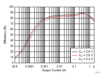
效率与输出电流间的关系(VOUT = 1.2V) |
|
空白 |
空白 |
|
![]() |
![]() |
Changes from G Revision (September 2016) to H Revision
Changes from F Revision (January 2015) to G Revision
Changes from E Revision (February 2014) to F Revision
Changes from D Revision (June 2013) to E Revision
Changes from C Revision (May 2013) to D Revision
Changes from B Revision (July 2012) to C Revision
Changes from A Revision (November 2011) to B Revision
Changes from * Revision (October 2011) to A Revision
PART NUMBER(1) | INPUT VOLTAGE | OUTPUT CURRENT | Power Good Logic Level (EN=Low) |
---|---|---|---|
TLV62080 | 2.5 V to 6 V | 1.2 A | High Impedance |
TLV62084 | 2.7 V to 6 V | 2 A | High Impedance |
TLV62084A | 2.7 V to 6 V | 2 A | Low |
space
space
space
MIN | MAX | UNIT | ||
---|---|---|---|---|
Voltage range(2) | VIN, PG, VOS | – 0.3 | 7 | V |
SW | – 0.3 | VIN + 0.3 | V | |
SW (AC, less than 10 ns)(3) | – 3.0 | 10 | V | |
FB | – 0.3 | 3.6 | V | |
EN | – 0.3 | VIN + 0.3 | V | |
Power Good Sink Current | PG | 1 | mA | |
Operating junction temperature range, TJ | – 40 | 150 | °C | |
Storage temperature range, Tstg | – 65 | 150 | °C |
VALUE | UNIT | |||
---|---|---|---|---|
V(ESD) | Electrostatic discharge | Human body model (HBM) ESD stress voltage(1) | ±2000 | V |
Charged device model (CDM) ESD stress voltage(2) | ±500 | V |
MIN | TYP | MAX | UNIT | ||
---|---|---|---|---|---|
VIN | Input voltage range, TLV62080 | 2.5 | 6 | V | |
VIN | Input voltage range, TLV62084, TLV62084A | 2.7 | 6 | V | |
TJ | Operating junction temperature | –40 | 125 | °C |
THERMAL METRIC(1) | TLV6208x DSG (8 PINS) |
UNITS | |
---|---|---|---|
θJA | Junction-to-ambient thermal resistance | 59.7 | °C/W |
θJCtop | Junction-to-case (top) thermal resistance | 70.1 | °C/W |
θJB | Junction-to-board thermal resistance | 30.9 | °C/W |
ψJT | Junction-to-top characterization parameter | 1.4 | °C/W |
ψJB | Junction-to-board characterization parameter | 31.5 | °C/W |
θJCbot | Junction-to-case (bottom) thermal resistance | 8.6 | °C/W |
See Typical Application for characterization setup.
space
FIGURE | ||
---|---|---|
Efficiency | Load current, VOUT = 0.9 V | Figure 1 |
Load current, VOUT = 1.2 V | Figure 2 | |
Load current, VOUT = 2.5 V | Figure 3 | |
Output Voltage Accuracy | Input Voltage, VOUT = 0.9 V | Figure 4 |
Input Voltage, VOUT = 2.5 V | Figure 5 | |
Load current, VOUT = 0.9 V | Figure 6 | |
Load current, VOUT = 2.5 V | Figure 7 | |
Switching Frequency | Load current, VOUT = 2.5 V | Figure 8 |
VOUT = 0.9 V | ||
VOUT = 2.5 V | ||
VOUT = 1.2 V | ||
VOUT = 0.9 V | ||
The TLV62080 and TLV62084x synchronous switched-mode converters are based on DCS-Control™. DCS-Control™ is an advanced regulation topology that combines the advantages of hysteretic and voltage mode control.
The DCS-Control™ topology operates in PWM (pulse width modulation) mode for medium to heavy load conditions and in power save mode at light load currents. In PWM mode, the TLV6208x converter operates with the nominal switching frequency of 2 MHz, having a controlled frequency variation over the input voltage range. As the load current decreases, the converter enters power save mode, reducing the switching frequency and minimizing the IC quiescent current to achieve high efficiency over the entire load current range. DCS-Control™ supports both operation modes (PWM and PFM) using a single building block with a seamless transition from PWM to power save mode without effects on the output voltage. The TLV62080 and TLV62084x devices offer both excellent DC voltage and superior load transient regulation, combined with very low output voltage ripple, minimizing interference with RF circuits.
The devices offer low input-to-output voltage difference by entering the 100% duty-cycle mode. In this mode the high-side MOSFET switch is constantly turned on and the low-side MOSFET is switched off. This mode is particularly useful in battery powered applications to achieve the longest operation time by taking full advantage of the whole battery voltage range. Equation 1 calculates the minimum input voltage to maintain regulation based on the load current and output voltage.
space
where
space
The device is enabled by setting the EN input to a logic HIGH. Accordingly, a logic LOW disables the device. If the device is enabled, the internal power stage starts switching and regulates the output voltage to the programmed threshold. The EN input must be terminated and not left floating.
The output gets discharged through the SW terminal with a typical discharge resistor of RDIS whenever the device shuts down (by disable, thermal shutdown or UVLO).
When EN is set to start device operation, the device starts switching after a delay of about 40 μs and VOUT rises with a slope of about 10mV/μs (See Figure 16 and Figure 17 for typical startup operation). Soft start avoids excessive inrush current and creates a smooth output voltage rise slope. Soft start also prevents excessive voltage drops of primary cells and rechargeable batteries with high internal impedance.
If the output voltage is not reached within the soft start time, such as in the case of heavy load, the converter enters standard operation. Consequently, the inductor current limit operates as described in Inductor Current-Limit. The TLV62080 and TLV62084x devices are able to start into a pre-biased output capacitor. The converter starts with the applied bias voltage and ramps the output voltage to the nominal value.
The TLV62080 and TLV62084x devices have a power-good output going low when the output voltage is below the nominal value. The power good maintains high impedance once the output is above 95% of the regulated voltage, and is driven to low once the output voltage falls below typically 90% of the regulated voltage. The PG terminal is an open drain output and is specified to sink typically up to 0.5 mA. The power good output requires a pull-up resistor which is recommended connecting to the device output. When the device is off because of disable, UVLO, or thermal shutdown, the PG terminal is at high impedance. TLV62084A features PG=Low in these cases. Table 2 and Table 3 show the different PG operation for the TLV6208x and TLV62084A. The PG output can be left floating if unused.
space
Device Information | PG Logic Status | ||
High Z | Low | ||
Enable (EN=High) | VFB ≥ VPG | √ | |
VFB ≤ VPG | √ | ||
Shutdown (EN=Low) | √ | ||
UVLO | 0.7V < VIN < VUVLO | √ | |
Thermal Shutdown | TJ > TJSD | √ | |
Power Supply Removal | VIN < 0.7V | √ |
space
Device Information | PG Logic Status | ||
High Z | Low | ||
Enable (EN=High) | VFB ≥ VPG | √ | |
VFB ≤ VPG | √ | ||
Shutdown (EN=Low) | √ | ||
UVLO | 0.7V < VIN < VUVLO | √ | |
Thermal Shutdown | TJ > TJSD | √ | |
Power Supply Removal | VIN < 0.7V | √ |
space
The PG signal can be used for sequencing of multiple rails by connecting to the EN terminal of other converters. Leave the PG terminal unconnected when not in use.
To avoid misoperation of the device at low input voltages, an undervoltage lockout is implemented which shuts down the device at voltages lower than VUVLO with a VHYS_UVLO hysteresis.
The device goes into thermal shutdown once the junction temperature exceeds typically TJSD. Once the device temperature falls below the threshold, the device returns to normal operation automatically.
The Inductor current-limit prevents the device from high inductor current and drawing excessive current from the battery or input voltage rail. Excessive current can occur with a shorted or saturated inductor, a heavy load, or shorted output circuit condition.
The incorporated inductor peak-current limit measures the current during the high-side and low-side power MOSFET on-phase. Once the high-side switch current-limit is tripped, the high-side MOSFET is turned off and the low-side MOSFET is turned on to reduce the inductor current. When the inductor current drops down to the low-side switch current-limit, the low-side MOSFET is turned off and the high-side switch is turned on again. This operation repeats until the inductor current does not reach the high-side switch current-limit. Because of an internal propagation delay, the real current-limit value exceeds the static-current limit in the Electrical Characteristics table.
As the load current decreases, the TLV62080 and TLV62084x devices enter power save mode operation. During power save mode, the converter operates with a reduced switching frequency in PFM mode and with a minimum quiescent current maintaining high efficiency. Power save mode occurs when the inductor current becomes discontinuous. Operation in power save mode is based on a fixed on time architecture. The typical on time is given by ton = 400 ns × (VOUT / VIN). The switching frequency over the whole load current range is shown in Figure 8.
NOTE
Information in the following applications sections is not part of the TI component specification, and TI does not warrant its accuracy or completeness. TI’s customers are responsible for determining suitability of components for their purposes. Customers should validate and test their design implementation to confirm system functionality.
The devices are designed to operate from an input voltage supply range between 2.5 V (2.7 V for the TLV62084x devices) and 6 V with a maximum output current of 2 A (1.2 A for the TLV62080 device). The TLV6208x devices operate in PWM mode for medium to heavy load conditions and in power save mode at light load currents.
In PWM mode the TLV6208x converters operate with the nominal switching frequency of 2 MHz which provides a controlled frequency variation over the input voltage range. As the load current decreases, the converter enters power save mode, reducing the switching frequency and minimizing the IC quiescent current to achieve high efficiency over the entire load current range.
The WEBENCH software uses an iterative design procedure and accesses a comprehensive database of components when generating a design. See the 文档支持 section for additional documentation.
Use the following typical application design procedure to select external components values for the TLV62084 device.
DESIGN PARAMETERS | EXAMPLE VALUES |
---|---|
Input Voltage Range | 2.8 V to 4.2 V |
Output Voltage | 1.2 V |
Transient Response | ±5% VOUT |
Input Voltage Ripple | 400 mV |
Output Voltage Ripple | 30 mV |
Output Current Rating | 2 A |
Operating frequency | 2 MHz |
Click here to create a custom design using the TLV62080 device with the WEBENCH® Power Designer.
The WEBENCH Power Designer provides a customized schematic along with a list of materials with real-time pricing and component availability.
In most cases, these actions are available:
Get more information about WEBENCH tools at www.ti.com/WEBENCH.
REFERENCE | DESCRIPTION | MANUFACTURER(1) |
---|---|---|
C1 | 10 μF, Ceramic Capacitor, 6.3 V, X5R, size 0603 | Std |
C2 | 22 μF, Ceramic Capacitor, 6.3 V, X5R, size 0805, GRM21BR60J226ME39L | Murata |
C3 | 47 μF, Tantalum Capacitor, 8 V, 35 mΩ, size 3528, T520B476M008ATE035 | Kemet |
L1 | 1 μH, Power Inductor, 2.2 A, size 3 mm × 3 mm × 1.2 mm, XFL3012-102MEB | Coilcraft |
R1 | 65.3 kΩ, Chip Resistor, 1/16 W, 1%, size 0603 | Std |
R2 | 39.2 kΩ, Chip Resistor, 1/16 W, 1%, size 0603 | Std |
R3 | 178 kΩ, Chip Resistor, 1/16 W, 1%, size 0603 | Std |
The inductor and the output capacitor together provide a low pass frequency filter. To simplify this process Table 6 outlines possible inductor and capacitor value combinations for the most application.
L [µH](3) | COUT [µF](3) | ||||
---|---|---|---|---|---|
10 | 22 | 47 | 100 | 150 | |
0.47 | |||||
1 | + | +(1)(2) | + | + | |
2.2 | + | + | + | + | |
4.7 |
The main parameter for the inductor selection is the inductor value and then the saturation current of the inductor. To calculate the maximum inductor current under static load conditions, Equation 2 is given.
where
space
TI recommends choosing the saturation current for the inductor 20% to approximately 30% higher than the IL,MAX, out of Equation 2. A higher inductor value is also useful to lower ripple current, but increases the transient response time as well. The following inductors are recommended to be used in designs (see Table 7).
INDUCTANCE [µH] |
CURRENT RATING [mA] |
DIMENSIONS L x W x H [mm3] |
DC RESISTANCE [mΩ typ] |
TYPE | MANUFACTURER(2) |
---|---|---|---|---|---|
1 | 2500 | 3 × 3 × 1.2 | 35 | XFL3012-102ME | Coilcraft |
1 | 1650(1) | 3 × 3 × 1.2 | 40 | LQH3NPN1R0NJ0 | Murata |
2.2 | 2500 | 4 × 3.7 × 1.65 | 49 | LQH44PN2R2MP0 | Murata |
2.2 | 1600(1) | 3 × 3 × 1.2 | 81 | XFL3012-222ME | Coilcraft |
The input capacitor is the low impedance energy source for the converter which helps to provide stable operation. A low ESR multilayer ceramic capacitor is recommended for best filtering and must be placed between VIN and GND as close as possible to those terminals. For most applications 10 μF is sufficient though a larger value reduces input current ripple.
The architecture of the TLV6208x device allows use of tiny ceramic-type output capacitors with low equivalent-series resistance (ESR). These capacitors provide low output voltage ripple and are recommended. To keep the resistance up to high frequencies and to get narrow capacitance variation with temperature, TI recommends use of the X7R or X5R dielectric. The TLV62080 and TLV62084x devices are designed to operate with an output capacitance of 10 to 100 µF and beyond, as listed in Table 6. Load transient testing and measuring the bode plot are good ways to verify stability with larger capacitor values.
CAPACITANCE [µF] |
TYPE | DIMENSIONS L x W x H [mm3] |
MANUFACTURER(1) |
---|---|---|---|
10 | GRM188R60J106M | 0603: 1.6 × 0.8 × 0.8 | Murata |
22 | GRM188R60G226M | 0603: 1.6 × 0.8 × 0.8 | Murata |
22 | GRM21BR60J226M | 0805: 2 × 1.2 × 1.25 | Murata |
By selecting R1 and R2, the output voltage is programmed to the desired value. Use Equation 3 to calculate R1 and R2.
space
For best accuracy, R2 must be kept smaller than 40 kΩ to ensure that the current flowing through R2 is at least 100-times larger than IFB. Changing the sum towards a lower value increases the robustness against noise injection. Changing the sum towards higher values reduces the current consumption.
VIN = 3.3 to 4.2 V | VOUT = 1.2 V | ILOAD = 2.2 Ω |
VIN = 3.3 V | VOUT = 1.2 V | |
VIN = 3.3 V | VOUT = 1.2 V | ILOAD = 2.2 Ω |
The input power supply's output current needs to be rated according to the supply voltage, output voltage and output current of the TLV6208x.
The PCB layout is an important step to maintain the high performance of the TLV62080 and TLV62084x devices.
Implementation of integrated circuits in low-profile and fine-pitch surface-mount packages typically requires special attention to power dissipation. Many system-dependent issues such as thermal coupling, airflow, added heat sinks and convection surfaces, and the presence of other heat-generating components affect the power-dissipation limits of a given component.
Three basic approaches for enhancing thermal performance are listed below:
For more details on how to use the thermal parameters, see the Thermal Characteristics application notes SZZA017 and SPRA953.
TI'S PUBLICATION OF INFORMATION REGARDING THIRD-PARTY PRODUCTS OR SERVICES DOES NOT CONSTITUTE AN ENDORSEMENT REGARDING THE SUITABILITY OF SUCH PRODUCTS OR SERVICES OR A WARRANTY, REPRESENTATION OR ENDORSEMENT OF SUCH PRODUCTS OR SERVICES, EITHER ALONE OR IN COMBINATION WITH ANY TI PRODUCT OR SERVICE.
请单击此处,借助 WEBENCH® Power Designer 并使用 TLV62080 器件定制设计方案
WEBENCH Power Designer 提供一份定制原理图以及罗列实时价格和组件可用性的物料清单。
在多数情况下,可执行以下操作:
有关 WEBENCH 工具的详细信息,请访问 www.ti.com/WEBENCH。
相关文档请参见以下部分:
下面的表格列出了快速访问链接。范围包括技术文档、支持与社区资源、工具和软件,并且可以快速访问样片或购买链接。
DCS-Control, E2E are trademarks of Texas Instruments.
WEBENCH is a registered trademark of Texas Instruments.
DCS-Control is a trademark of TI.
All other trademarks are the property of their respective owners.
ESD 可能会损坏该集成电路。德州仪器 (TI) 建议通过适当的预防措施处理所有集成电路。如果不遵守正确的处理措施和安装程序 , 可能会损坏集成电路。
ESD 的损坏小至导致微小的性能降级 , 大至整个器件故障。 精密的集成电路可能更容易受到损坏 , 这是因为非常细微的参数更改都可能会导致器件与其发布的规格不相符。
如需接收文档更新通知,请访问 www.ti.com.cn 网站上的器件产品文件夹。点击右上角的提醒我 (Alert me) 注册后,即可每周定期收到已更改的产品信息。有关更改的详细信息,请查阅已修订文档中包含的修订历史记录。
The following links connect to TI community resources. Linked contents are provided "AS IS" by the respective contributors. They do not constitute TI specifications and do not necessarily reflect TI's views; see TI's Terms of Use.
SLYZ022 — TI Glossary.
This glossary lists and explains terms, acronyms, and definitions.
以下页中包括机械、封装和可订购信息。这些信息是针对指定器件可提供的最新数据。这些数据会在无通知且不对本文档进行修订的情况下发生改变。欲获得该数据表的浏览器版本,请查阅左侧的导航栏。
德州仪器(TI) 及其下属子公司有权根据 JESD46 最新标准, 对所提供的产品和服务进行更正、修改、增强、改进或其它更改, 并有权根据 JESD48最新标准中止提供任何产品和服务。客户在下订单前应获取最新的相关信息, 并验证这些信息是否完整且是最新的。所有产品的销售都遵循在订单确认时所提供的TI 销售条款与条件。
TI 保证其所销售的组件的性能符合产品销售时 TI 半导体产品销售条件与条款的适用规范。仅在 TI 保证的范围内,且 TI 认为有必要时才会使用测试或其它质量控制技术。除非适用法律做出了硬性规定,否则没有必要对每种组件的所有参数进行测试。
TI 对应用帮助或客户产品设计不承担任何义务。客户应对其使用 TI 组件的产品和应用自行负责。为尽量减小与客户产品和应用相关的风险,客户应提供充分的设计与操作安全措施。
TI 不对任何 TI 专利权、版权、屏蔽作品权或其它与使用了 TI 组件或服务的组合设备、机器或流程相关的 TI 知识产权中授予 的直接或隐含权限作出任何保证或解释。TI所发布的与第三方产品或服务有关的信息,不能构成从 TI 获得使用这些产品或服 务的许可、授权、或认可。使用此类信息可能需要获得第三方的专利权或其它知识产权方面的许可,或是 TI 的专利权或其它知识产权方面的许可。
对于 TI 的产品手册或数据表中 TI 信息的重要部分,仅在没有对内容进行任何篡改且带有相关授权、条件、限制和声明的情况 下才允许进行复制。TI 对此类篡改过的文件不承担任何责任或义务。复制第三方的信息可能需要服从额外的限制条件。
在转售 TI 组件或服务时,如果对该组件或服务参数的陈述与 TI 标明的参数相比存在差异或虚假成分,则会失去相关 TI 组件或服务的所有明示或暗示授权,且这是不正当的、欺诈性商业行为。TI 对任何此类虚假陈述均不承担任何责任或义务。
客户认可并同意,尽管任何应用相关信息或支持仍可能由 TI 提供,但他们将独力负责满足与其产品及在其应用中使用 TI 产品相关的所有法律、法规和安全相关要求。客户声明并同意,他们具备制定与实施安全措施所需的全部专业技术和知识,可预见故障的危险后果、监测故障及其后果、降低有可能造成人身伤害的故障的发生机率并采取适当的补救措施。客户将全额赔偿因 在此类安全关键应用中使用任何 TI 组件而对 TI及其代理造成的任何损失。
在某些场合中,为了推进安全相关应用有可能对 TI 组件进行特别的促销。TI 的目标是利用此类组件帮助客户设计和创立其特有的可满足适用的功能安全性标准和要求的终端产品解决方案。尽管如此,此类组件仍然服从这些条款。
TI 组件未获得用于 FDA Class III(或类似的生命攸关医疗设备)的授权许可,除非各方授权官员已经达成了专门管控此类使 用的特别协议。
只有那些 TI 特别注明属于军用等级或“增强型塑料”的 TI 组件才是设计或专门用于军事/航空应用或环境的。购买者认可并同 意,对并非指定面向军事或航空航天用途的 TI组件进行军事或航空航天方面的应用,其风险由客户单独承担,并且由客户独 力负责满足与此类使用相关的所有法律和法规要求。
TI 已明确指定符合 ISO/TS16949 要求的产品,这些产品主要用于汽车。在任何情况下,因使用非指定产品而无法达到 ISO/TS16949要求,TI不承担任何责任。
德州仪器在线技术支持社区: www.deyisupport.com
邮寄地址: 上海市浦东新区世纪大道1568 号,中建大厦32 楼邮政编码: 200122
Copyright© 2016, 德州仪器半导体技术(上海)有限公司