• Menu
  • Product
  • Email
  • PDF
  • Order now
  • bq76925 用于 3 至 6 节串联锂离子/锂聚合物电池保护和电量监测的主机控制模拟前端 应用

    • ZHCS327D July   2011  – October 2016 BQ76925

      PRODUCTION DATA.  

  • CONTENTS
  • SEARCH
  • bq76925 用于 3 至 6 节串联锂离子/锂聚合物电池保护和电量监测的主机控制模拟前端 应用
  1. 1 特性
  2. 2 应用
  3. 3 说明
  4. 4 修订历史记录
  5. 5 说明 (续)
  6. 6 Pin Configuration and Functions
  7. 7 Specifications
    1. 7.1  Absolute Maximum Ratings
    2. 7.2  ESD Ratings
    3. 7.3  Recommended Operating Conditions
    4. 7.4  Thermal Information
    5. 7.5  Electrical Characteristics: Supply Current
    6. 7.6  Internal Power Control (Startup and Shutdown)
    7. 7.7  3.3-V Voltage Regulator
    8. 7.8  Voltage Reference
    9. 7.9  Cell Voltage Amplifier
    10. 7.10 Current Sense Amplifier
    11. 7.11 Overcurrent Comparator
    12. 7.12 Internal Temperature Measurement
    13. 7.13 Cell Balancing and Open Cell Detection
    14. 7.14 I2C Compatible Interface
    15. 7.15 Typical Characteristics
  8. 8 Detailed Description
    1. 8.1 Overview
    2. 8.2 Functional Block Diagram
    3. 8.3 Feature Description
      1. 8.3.1 Internal LDO Voltage Regulator
      2. 8.3.2 ADC Interface
        1. 8.3.2.1 Reference Voltage
          1. 8.3.2.1.1 Host ADC Calibration
        2. 8.3.2.2 Cell Voltage Monitoring
          1. 8.3.2.2.1 Cell Amplifier Headroom Under Extreme Cell Imbalance
          2. 8.3.2.2.2 Cell Amplifier Headroom Under BAT Voltage Drop
        3. 8.3.2.3 Current Monitoring
        4. 8.3.2.4 Overcurrent Monitoring
        5. 8.3.2.5 Temperature Monitoring
          1. 8.3.2.5.1 Internal Temperature Monitoring
      3. 8.3.3 Cell Balancing and Open Cell Detection
    4. 8.4 Device Functional Modes
      1. 8.4.1 Power Modes
        1. 8.4.1.1 POWER ON RESET (POR)
        2. 8.4.1.2 STANDBY
        3. 8.4.1.3 SLEEP
    5. 8.5 Programming
      1. 8.5.1 Host Interface
        1. 8.5.1.1 I2C Addressing
        2. 8.5.1.2 Bus Write Command to bq76925
        3. 8.5.1.3 Bus Read Command from bq76925 Device
    6. 8.6 Register Maps
      1. 8.6.1 Register Descriptions
  9. 9 Application and Implementation
    1. 9.1 Application Information
      1. 9.1.1 Recommended System Implementation
        1. 9.1.1.1 Voltage, Current, and Temperature Outputs
        2. 9.1.1.2 Power Management
        3. 9.1.1.3 Low Dropout (LDO) Regulator
        4. 9.1.1.4 Input Filters
        5. 9.1.1.5 Output Filters
      2. 9.1.2 Cell Balancing
    2. 9.2 Typical Application
      1. 9.2.1 Design Requirements
      2. 9.2.2 Detailed Design Procedure
      3. 9.2.3 Application Curves
  10. 10Power Supply Recommendations
  11. 11Layout
    1. 11.1 Layout Guidelines
    2. 11.2 Layout Example
  12. 12器件和文档支持
    1. 12.1 文档支持
      1. 12.1.1 相关文档
    2. 12.2 接收文档更新通知
    3. 12.3 社区资源
    4. 12.4 商标
    5. 12.5 静电放电警告
    6. 12.6 Glossary
  13. 13机械、封装和可订购信息
  14. 重要声明
search No matches found.
  • Full reading width
    • Full reading width
    • Comfortable reading width
    • Expanded reading width
  • Card for each section
  • Card with all content


DATA SHEET

bq76925 用于 3 至 6 节串联锂离子/锂聚合物电池保护和电量监测的主机控制模拟前端 应用

本资源的原文使用英文撰写。 为方便起见,TI 提供了译文;由于翻译过程中可能使用了自动化工具,TI 不保证译文的准确性。 为确认准确性,请务必访问 ti.com 参考最新的英文版本(控制文档)。

1 特性

  • 用于主机电芯测量的模拟接口
    • 电芯输入多路开关、电平转换器和缩放器
    • 经过校准的 1.5V/3.0V 低漂移基准电压,可实现精确模数转换
  • 用于主机电流测量的模拟接口
    • 可变增益电流感测放大器,能够与 1mΩ 感测电阻搭配运行
  • 用于主机温度测量的可切换热敏电阻偏置输出
  • 阈值可动态调节的过流比较器
    • 向主机报告潜在的过流故障
    • 在连接负载后唤醒主机
  • 集成电芯均衡场效应晶体管 (FET)
    • 单独主机控制
    • 每个电芯的均衡电流为 50mA
  • 支持电芯感测线路开路检测
  • 集成有用于为微控制器或 LED 供电的 3.3V 稳压器
  • 用于主机通信的 I2C 接口
    • 可选数据包循环冗余校验 (CRC),用于确保通信的稳健性
  • 电源电压范围:4.2V 至 26.4V
  • 低功耗
    • 正常模式下的电流典型值为 40µA
    • 休眠模式下的电流最大值为 1.5µA
  • 采用 20 引脚散热薄型小外形尺寸 (HTSSOP) 或 24 引脚超薄四方扁平无引线 (VQFN) 封装

2 应用

  • 锂离子电池组主保护
    • 无绳电动工具
    • 轻型电动车辆(电动自行车和电动踏板车等)
    • 不间断电源 (UPS) 系统
    • 医疗设备
    • 便携式测试设备

3 说明

Bq76925 是一款由主机控制的模拟前端 (AFE),它是一套完备电池组监视、均衡和保护系统的组成部分,这套系统适用于 3、4、5 或 6 节串联锂离子和锂聚合物电池。bq76925 器件通过一个主机控制器轻松监视各电芯电压、电池组电流及温度。主机可利用这些信息确定不安全或故障运行情况,例如过压、欠压、过热、过流、电芯电量失衡、充电状态和健康状况。

电芯输入电压经电平转换、多路选择、缩放后输出,以供主机 ADC 测量。一个专用引脚提供了经校准的低漂移基准电压,从而实现精确测量。

器件信息(1)

器件型号 封装 封装尺寸(标称值)
bq76925 TSSOP (20) 4.00mm x 4.00mm
bq76925 VQFN (24) 6.50mm x 4.40mm
  1. 要了解所有可用封装,请见数据表末尾的可订购产品附录。

简化电路原理图

bq76925 simplified_sch_lusam9.gif

4 修订历史记录

Changes from C Revision (July 2015) to D Revision

  • Added test condition n = 1 – 5 at 25°C and MAX value for IVCn parameterGo
  • Added 接收文档更新通知部分Go

Changes from B Revision (December 2011) to C Revision

  • 已添加 ESD 额定值表,特性 说明 部分,器件功能模式,应用和实施部分,电源相关建议部分,布局部分,器件和文档支持部分以及机械、封装和可订购信息部分.Go
  • 已将内容移至新的部分,并已添加相应部分、图、表和文档的超链接。Go
  • Moved RBAT, CBAT, RIN, CIN, RSENSEN, RSENSEP, CSENSE, RVCTL, CV3P3, CREF, and COUT table rows to Design RequirementsGo

Changes from A Revision (July 2011) to B Revision

  • Added 24-pin QFN (RGE) Package to Production DataGo

Changes from * Revision (July 2011) to A Revision

  • Changed literature number to Rev A for ProductMix releaseGo

5 说明 (续)

外部感测电阻两端的电压经过放大后输出到主机 ADC,以进行充放电电流测量。两种增益设置使得器件能够搭配多种感测电阻值使用,以便在各种电池组电流下运行。

为了使主机能够进行温度测量,AFE 提供了一个单独的输出引脚,用于为外部热敏电阻网络提供偏置。该输出可在主机的控制下打开/关闭,从而将功耗降至最小。

bq76925 器件包含一个阈值可动态选择的比较器,用于监视电流。比较器结果通过开漏输出驱动,以在超过阈值时向主机报警。该特性可用于在连接负载后唤醒主机,或者向主机报告潜在的故障情况。

bq76925 器件集成了完全受主机控制的电芯均衡 FET。均衡电流通过外部电阻设置,最高可设为 50mA。可以将这些相同的 FET 与电芯电压测量结果搭配使用,以检测电芯检测线路上的开路情况。

主机通过 I2C 接口与 AFE 通信。可以选择使用数据包 CRC 以确保通信的稳健性。可以通过 I2C 接口将器件置于低电流休眠模式,并且可以通过上拉 ALERT 引脚唤醒器件。

6 Pin Configuration and Functions

PW Package
20-Pin TTSOP
Top View
bq76925 pos_lusam9.gif
RGE Package
24-Pin QFN With Thermal Pad
Top View
bq76925 po_lusam9_qfn.gif

Pin Functions

NAME PIN NO. TYPE DESCRIPTION
TSSOP VQFN
VCTL 1 23 Output 3.3-V Regulator control voltage(1)
ALERT 13 13 Output Overcurrent alert (open drain)
BAT 2 24 Power Supply voltage, tied to most positive cell
NC — 9, 10, 21, 22 — No Connection (leave open)
SCL 19 19 Input I2C Clock (open drain)
SDA 18 18 Input / Output I2C Data (open drain)
SENSEN 11 11 Input Negative current sense
SENSEP 12 12 Input Positive current sense
V3P3 20 20 Output 3.3-V Regulator
VC6 3 1 Input Sense voltage for most positive cell
VC5 4 2 Input Sense voltage for second most positive cell
VC4 5 3 Input Sense voltage for third most positive cell
VC3 6 4 Input Sense voltage for fourth most positive cell
VC2 7 5 Input Sense voltage for fifth most positive cell
VC1 8 6 Input Sense voltage for least positive cell
VC0 9 7 Input Sense voltage for negative end of cell stack
VCOUT 15 15 Output Cell measurement voltage
VIOUT 14 14 Output Current measurement voltage
VREF 17 17 Output Reference voltage for ADC
VSS 10 8 Power Ground
VTB 16 16 Output Bias voltage for thermistor network
(1) When a bypass FET is used to supply the regulated 3.3-V load current, VCTL automatically adjusts to keep V3P3 = 3.3 V. If VCTL is tied to BAT, the load current is supplied through V3P3.

7 Specifications

7.1 Absolute Maximum Ratings

over operating free-air temperature range (unless otherwise noted) (1)
MIN MAX UNIT
VBAT Supply voltage BAT –0.3 36 V
VI Input voltage Cell input differential, VCn to VCn+1, n = 0 to 5 –0.3 9 V
Cell input, VCn, n = 1 to 6 –0.3 (6 × n)
BAT to VC6 differential –10 10
VC0 (2) –3 3
SENSEP, SENSEN –3 3
SCL, SDA –0.3 6
VO Output voltage VCOUT, VIOUT, VREF –0.3 3.6 V
VTB, V3P3 –0.3 7
ALERT –0.3 30
VCTL –0.3 36
ICB Cell balancing current 70 mA
IIN Cell input current –25 70 mA
Tstg Storage temperature –65 150 °C
(1) Stresses beyond those listed under Absolute Maximum Ratings may cause permanent damage to the device. These are stress ratings only, which do not imply functional operation of the device at these or any other conditions beyond those indicated under Recommended Operating Conditions. Exposure to absolute-maximum-rated conditions for extended periods may affect device reliability.
(2) Negative voltage swings on VC0 in the absolute maximum range can cause unwanted circuit behavior and should be avoided.

7.2 ESD Ratings

VALUE UNIT
V(ESD) Electrostatic discharge Human-body model (HBM), per ANSI/ESDA/JEDEC JS-001(1) ±2000 V
Charged-device model (CDM), per JEDEC specification JESD22-C101(2) ±500
(1) JEDEC document JEP155 states that 500-V HBM allows safe manufacturing with a standard ESD control process.
(2) JEDEC document JEP157 states that 250-V CDM allows safe manufacturing with a standard ESD control process.

7.3 Recommended Operating Conditions(1)

MIN NOM MAX UNIT
Supply voltage BAT 4.2 26.4 V
VI Input voltage Cell input differential, VCn to VCn+1, n = 0 to 5 1.4 4.4 V
Cell input, VCn, n = 1 to 6 4.4 × n V
BAT to VC6 differential –8 8 V
VC0, SENSEN 0 V
SENSEP –125 375 mV
SCL, SDA 0 5.5 V
V3P3 Backfeeding(2) 5.5 V
ALERT Wakeup function 0 26.4 V
VO Output voltage VCOUT, VIOUT 0 V3P3 + 0.2 V
VREF REFSEL = 0 1.5 V
REFSEL = 1 3 V
VTB 5.5 V
V3P3 Regulating 3.3 V
VCTL 0.8 26.4 V
ALERT Alert function 0 5.5 V
ICB Cell balancing current 0 50 mA
TA Operating free-air temperature –25 85 °C
TFUNC Functional free-air temperature –40 100 °C
(1) All voltages are relative to VSS, except “Cell input differential.”
(2) Internal 3.3-V regulator may be overridden (that is, backfed) by applying an external voltage larger than the regulator voltage.

7.4 Thermal Information

THERMAL METRIC(1) bq76925 UNIT
PW (TSSOP) RGE (VQFN)
20 PINS 24 PINS
RθJA Junction-to-ambient thermal resistance 97.5 36 °C/W
RθJC (top) Junction-to-case (top) thermal resistance 31.7 38.6 °C/W
RθJB Junction-to-board thermal resistance 48.4 14 °C/W
ψJT Junction-to-top characterization parameter 1.5 0.6 °C/W
ψJB Junction-to-board characterization parameter 47.9 14 °C/W
RθJC (bot) Junction-to-case (bottom) thermal resistance n/a 4.6 °C/W
(1) For more information about traditional and new thermal metrics, see the Semiconductor and IC Package Thermal Metrics application report.

7.5 Electrical Characteristics: Supply Current

BAT = 4.2 to 26.4 V, VCn = 1.4 to 4.4, TA = –25°C to +85°C
Typical values stated where TA = 25°C and BAT= 21.6 V (unless otherwise noted)
PARAMETER TEST CONDITION MIN TYP MAX UNIT
IDD1 Normal mode supply current All device functions enabled
All pins unloaded
SDA and SCL high
40 48 µA
IDD2 Standby mode 1 supply current V3P3 and overcurrent monitor enabled
All pins unloaded
All other device functions disabled
SDA and SCL high
14 17 µA
IDD3 Standby mode 2 supply current V3P3 enabled
All pins unloaded
All device functions disabled
SDA and SCL high
12 14 V
IDD4 Sleep mode supply current V3P3 disabled
All pins unloaded
All device functions disabled
SDA and SCL low
1 1.5 µA
IVCn Input current for selected cell All cell voltages equal
Cell balancing disabled
Open cell detection disabled
during cell voltage monitoring
n = 6 2.4 2.7 µA
n = 1 – 5 < 0.5
n = 1 – 5 at 25°C < 0.3
∆IVCn Cell to cell input current difference All cell voltages equal
Cell balancing disabled
Open cell detection disabled
< 0.2 µA

7.6 Internal Power Control (Startup and Shutdown)

PARAMETER TEST CONDITION MIN TYP MAX UNIT
VPOR Power on reset voltage Measured at BAT pin Initial BAT < 1.4 VBAT rising(1) 4.3 4.5 4.7 V
Initial BAT > 1.4 VBAT rising(1) 6.5 7 7.5 V
VSHUT Shutdown voltage(2) Measured at BAT pin, BAT falling 3.6 V
tPOR Time delay after POR before I2C comms allowed CV3P3 = 4.7 µF 1 ms
VWAKE Wakeup voltage Measured at ALERT pin 0.8 2 V
tWAKE_PLS Wakeup signal pulse width 1 5 μs
tWAKE_DLY Time delay after wakeup before I2C comms allowed CV3P3 = 4.7 µF 1 ms
(1) Initial power up will start with BAT < 1.4 V, however if BAT falls below VSHUT after rising above VPOR, the power on threshold depends on the minimum level reached by BAT after falling below VSHUT.
(2) Following POR, the device will operate down to this voltage.

7.7 3.3-V Voltage Regulator

PARAMETER TEST CONDITION MIN TYP MAX UNIT
VCTL Regulator control voltage (1)(2) Measured at VCTL, V3P3 regulating 3.3 26.4 V
VV3P3 Regulator output Measured at V3P3, IREG = 0 to 4 mA,
BAT = 4.2 to 26.4 V
3.2 3.3 3.4 V
IREG V3P3 output current 4 mA
ISC V3P3 short circuit current limit V3P3 = 0.0 V 10 17 mA
VTB Thermistor bias voltage Measured at VTB, ITB = 0 VV3P3 V
ITB Thermistor bias current 1 mA
RTB Thermistor bias internal resistance RDS(ON) for internal FET switch, ITB = 1 mA 90 130 Ω
(1) When a bypass FET is used to supply the regulated 3.3 V load current, VCTL automatically adjusts to keep V3P3 = 3.3 V. Note that VCTL,MIN and the FET VGS will determine the minimum BAT voltage at which the bypass FET will operate.
(2) If VCTL is tied to BAT, the load current is supplied through V3P3.

7.8 Voltage Reference

PARAMETER TEST CONDITION MIN TYP MAX UNIT
VREF Voltage reference output Before gain correction,
TA = 25°C
REF_SEL = 0 1.44 1.56 V
REF_SEL = 1 2.88 3.12
After gain correction, (1)
TA = 25°C
REF_SEL = 0 –0.1% 1.5 +0.1%
REF_SEL = 1 –0.1% 3 +0.1%
VREF_CAL Reference calibration voltage Measured at VCOUT VCOUT_SEL = 2 –0.9% 0.5 × VREF +0.9% V
VCOUT_SEL = 3 –0.5% 0.85 × VREF +0.5%
(0.85 × VREF) – (0.5 × VREF) –0.3% 0.35 × VREF +0.3% V
∆VREF Voltage reference tolerance TA = 0 – 50°C –40 40 ppm/°C
IREF VREF output current 10 µA
(1) Gain correction factor determined at final test and stored in non-volatile storage. Gain correction is applied by Host controller.

7.9 Cell Voltage Amplifier

PARAMETER TEST CONDITION MIN TYP MAX UNIT
GVCOUT Cell voltage amplifier gain Measured from VCn
to VCOUT
REF_SEL = 0 –1.6% 0.3 1.5%
REF_SEL = 1 –1.6% 0.6 1.5%
OVCOUT Cell voltage amplifier offset Measured from VCn to VCOUT –16 15 mV
VCOUT Cell voltage amp output range (1) Measured at VCOUT,
VCn = 5 V
REF_SEL = 0 1.47 1.5 1.53 V
REF_SEL = 1 2.94 3 3.06 V
Measured at VCOUT,
VCn = 0 V
0 V
∆VCOUT Cell voltage amplifier accuracy VCn = 1.4 V to 4.4 V,
After correction, (2)
Measured at VCOUT (3)
REF_SEL = 1(4)
TA = 25°C –3 3 mV
TA = 0°C to 50°C –5 5
TA = –25°C to +85°C –8 8
IVCOUT VCOUT output current(5) 10 µA
tVCOUT Delay from VCn select to VCOUT Output step of 200 mV, COUT = 0.1 µF 100 µs
(1) For VCn values greater than 5 V, VCOUT clamps at approximately V3P3.
(2) Correction factor determined at final test and stored in non-volatile storage. Correction is applied by Host controller.
(3) Output referred. Input referred accuracy is calculated as ∆VCOUT / GVCOUT (for example, 3 / 0.6 = 5).
(4) Correction factors are calibrated for gain of 0.6. Tolerance at gain of 0.3 is approximately doubled. Contact TI for information on devices calibrated to a gain of 0.3.
(5) Max DC load for specified accuracy.

7.10 Current Sense Amplifier

PARAMETER TEST CONDITION MIN TYP MAX UNIT
GVIOUT Current sense amplifier gain Measured from SENSEN,
SENSEP to VIOUT
I_GAIN = 0 4
I_GAIN = 1 8
VIIN Current sense amp input range Measured from SENSEN,
SENSEP to VSS
–125 375 mV
VIOUT Current sense amp output range Measured at VIOUT REF_SEL = 0 0.25 1.25 V
REF_SEL = 1 0.5 2.5 V
Zero current output Measured at VIOUT
SENSEP = SENSEN
REF_SEL = 0 1 V
REF_SEL = 1 2 V
∆VIOUT Current amplifier accuracy –1% 1%
IVIOUT VIOUT output current (1) 10 µA
(1) Max DC load for specified accuracy

7.11 Overcurrent Comparator

PARAMETER TEST CONDITION MIN TYP MAX UNIT
VBAT_COMP Minimum VBAT for comparator operation(1) 5 V
GVCOMP Comparator amplifier gain Measured from SENSEP to comparator input 1
VITRIP Current comparator trip threshold(2) 25 400 mV
∆VITRIP Current comparator accuracy VITRIP = 25 mV –6 6 mV
VITRIP > 25 mV –10% 10% V
VOL_ALERT ALERT Output Low Logic IALERT = 1 mA 0.4 V
VOH_ALERT ALERT Output High Logic (3) NA NA NA
IALERT ALERT Pulldown current ALERT = 0.4 V, Output driving low 1 mA
IALERT_LKG ALERT Leakage current ALERT = 5 V, Output Hi-Z < 1 μA
tOC Comparator response time 100 µs
(1) The Overcurrent Comparator is not guaranteed to work when VBAT is below this voltage.
(2) Trip threshold selectable from 25, 50, 75, 100, 125, 150, 175, 200, 225, 250, 275, 300, 325, 350, 375 or 400 mV.
(3) This parameter NA because output is open drain.

7.12 Internal Temperature Measurement

PARAMETER TEST CONDITION MIN TYP MAX UNIT
VTEMP_INT Internal temperature voltage Measured at VCOUT, TINT = 25°C 1.15 1.2 1.25 V
∆VTEMP_INT Internal temperature voltage sensitivity –4.4 mV/°C

7.13 Cell Balancing and Open Cell Detection

PARAMETER TEST CONDITION MIN TYP MAX UNIT
RBAL Cell balancing internal resistance(1) RDS(ON) for VC1 internal FET switch, VCn = 3.6 V 1 3 5 Ω
RDS(ON) for internal VC2 to VC6 FET switch, VCn = 3.6 V 3 5.5 8
(1) Balancing current is not internally limited. The cell balancing operation is completely controlled by the Host processor, no automatic function or time-out is included in the part. Take care to ensure that balancing current through the part is below the maximum power dissipation limit. The Host algorithm is responsible for limiting thermal dissipation to package ratings.

7.14 I2C Compatible Interface

PARAMETERS MIN TYP MAX UNIT
DC PARAMETERS
VIL Input Low Logic Threshold 0.6 V
VIH Input High Logic Threshold 2.8 V
VOL Output Low Logic Drive IOL = 1 mA 0.20 V
IOL = 2.5 mA 0.40
VOH Output High Logic Drive (Not applicable due to open-drain outputs) N/A V
ILKG I2C Pin Leakage Pin = 5 V, Output in Hi-Z < 1 µA
AC PARAMETERS
tr SCL, SDA Rise Time 1000 ns
tf SCL, SDA Fall Time 300 ns
tw(H) SCL Pulse Width High 4 µs
tw(L) SCL Pulse Width Low 4.7 µs
tsu(STA) Setup time for START condition 4.7 µs
th(STA) START condition hold time after which first clock pulse is generated 4 µs
tsu(DAT) Data setup time 250 ns
th(DAT) Data hold time 0(1) µs
tsu(STOP) Setup time for STOP condition 4 µs
tsu(BUF) Time the bus must be free before new transmission can start 4.7 µs
t V Clock Low to Data Out Valid 900 ns
th(CH) Data Out Hold Time After Clock Low 0 ns
fSCL Clock Frequency 0 100 kHz
tWAKE I2C ready after transition to Wake Mode 2.5 ms
(1) Devices must provide internal hold time of at least 300 ns for the SDA signal-to-bridge of the undefined region of the falling edge of SCL.
bq76925 I2C_time_lusam9.gif Figure 1. I2C Timing

7.15 Typical Characteristics

bq76925 D001_SLUSAM9.gif
Figure 2. Normal Mode Supply Current
bq76925 D003_SLUSAM9.gif
Figure 4. Regulator Output With 4 mA Load
bq76925 D005_SLUSAM9.gif
Figure 6. 1.5-V VREF Output (Before Correction)
bq76925 D002_SLUSAM9.gif
Figure 3. Sleep Mode Supply Current
bq76925 D004_SLUSAM9.gif
Figure 5. Regulator Output With No Load
bq76925 D006_SLUSAM9.gif
Figure 7. 3-V VREF Output (Before Correction)

8 Detailed Description

8.1 Overview

The bq76925 Host-controlled analog front end (AFE) is part of a complete pack monitoring, balancing, and protection system for 3-series to 6-series cell Lithium batteries. The bq76925 allows a Host controller to easily monitor individual cell voltages, pack current, and temperature. The Host may use this information to detect and act on a fault condition caused when one or more of these parameters exceed the limits of the application. In addition, the Host may use this information to determine end-of-charge, end-of-discharge, and other gas-gauging and state of health conditions.

bq76925 host_cont_lusam9.gif Figure 8. Example of bq76925 With Host Controller

8.2 Functional Block Diagram

bq76925 fbd_lusam9.gif

8.3 Feature Description

8.3.1 Internal LDO Voltage Regulator

The bq76925 device provides a regulated 3.3-V supply voltage on the V3P3 pin for operating the device’s internal logic and interface circuitry. This regulator may also be used to directly power an external microcontroller or other external circuitry up to a limit of 4-mA load current. In this configuration, the VCTL pin is tied directly to the BAT pin. For applications requiring more than 4 mA, an external-bypass transistor may be used to supply the load current. In this configuration, the VCTL pin is tied to the gate of the bypass FET. These two configurations are show in Figure 9.

bq76925 LDO_reg_conf_lusam9.gif Figure 9. LDO Regulator Configurations

For the configuration of Figure 9b), a high-gain bypass device should be used to ensure stability. A bipolar PNP or p-channel FET bypass device may be used. Contact TI for recommendations.

The LDO regulator may be overridden (that is, back-fed) by an external-supply voltage greater than the regulated voltage on V3P3. In this configuration, the bq76925 internal logic and interface circuitry operates from the external supply and the internal 3.3-V regulator supplys no load current.

8.3.2 ADC Interface

The bq76925 device is designed to interface to a multi-channel analog-to-digital converter (ADC) located in an external Host controller, such as an MSP430 Microcontroller or equivalent. Three outputs provide voltage, current, and temperature information for measurement by the Host. In addition, the bq76925 device includes a low-drift calibrated 1.5 / 3 V reference that is output on a dedicated pin for use as the reference input to the ADC.

The gain and offset characteristics of the bq76925 device are measured during factory test and stored in non-volatile memory as correction factors. The Host reads these correction factors and applies them to the ADC conversion results in order to achieve high-measurement accuracy. In addition, the precise voltage reference of the bq76925 can be used to calibrate the gain and offset of the Host ADC.

8.3.2.1 Reference Voltage

The bq76925 device outputs a stable reference voltage for use by the Host ADC. A nominal voltage of 1.5 V or 3 V is selected through the REF_SEL bit in the CONFIG_2 register. The reference voltage is very stable across temperature, but the initial voltage may vary by ±4%. The variation from nominal is manifested as a gain error in the ADC conversion result. To correct for this error, offset and gain correction factors are determined at final test and stored in the non-volatile registers VREF_CAL and VREF_CAL_EXT. The Host reads the correction factors and applies them to the nominal reference voltage to arrive at the actual reference voltage as described under Cell Voltage Monitoring. After gain correction, the tolerance of the reference will be within ±0.1%.

8.3.2.1.1 Host ADC Calibration

All analog-to-digital converters have inherent gain and offset errors, which adversely affect measurement accuracy. Some microcontrollers may be characterized by the manufacturer and shipped with ADC gain and offset information stored on-chip. It is also possible for such characterization to be done by the end-user on loose devices prior to PCB assembly or as a part of the assembled PCB test.

For applications where such ADC characterization is not provided or is not practical, the bq76925 device provides a means for in-situ calibration of the Host ADC through setting of the VCOUT_SEL bits in the CELL_CTL register two scaled versions of the reference voltage, 0.5 × VREF and 0.85 × VREF, can be selected for output on the VCOUT pin for measurement by the Host ADC. Measuring both scaled voltages enables the Host to do a two-point calibration of the ADC and compensate for the ADC offset and gain in all subsequent ADC measurement results as shown in Figure 10.

Note that the calibration accuracy will be limited by the tolerance of the scaled reference-voltage output so that use of this method may not be effective. For these cases, TI recommends to use a higher-accuracy source for the two-point calibration shown in Figure 10.

bq76925 ADC_calib_lusam9.gif Figure 10. Host ADC Calibration Using VREF

8.3.2.2 Cell Voltage Monitoring

The cell-voltage monitoring circuits include an input level-shifter, multiplexer (MUX), and scaling amplifier. The Host selects one VCn cell input for measurement by setting the VCOUT_SEL and CELL_SEL bits in the CELL_CTL register. The scaling factor is set by the REF_SEL bit in the CONFIG_2 register. The selected cell input is level shifted to VSS reference, scaled by a nominal gain GVCOUT = 0.3 (REF_SEL = 0) or 0.6 (REF_SEL = 1) and output on the VCOUT pin for measurement by the Host ADC.

Similar to the reference voltage, gain and offset correction factors are determined at final test for each individual cell input and stored in non-volatile registers VCn_CAL (n = 1-6) and VC_CAL_EXT_m (m = 1-2). These factors are read by the Host and applied to the ADC voltage-measurement results in order to obtain the specified accuracy.

The cell voltage offset and gain correction factors are stored as 5-bit signed integers in 2’s complement format. The most significant bits (VCn_OC_4, VCn_GC_4) are stored separately and must be concatenated with the least significant bits (VCn_OFFSET_CORR, VCn_GAIN_CORR).

The reference voltage offset and gain correction factors are stored respectively as a 6-bit and 5-bit signed integer in 2’s complement format. As with the cell voltage correction factors, the most significant bits (VREF_OC_5, VREF_OC_4, VREF_GC_4) are stored separately and must be concatenated with the least significant bits (VREF_OFFSET_CORR, VREF_GAIN_CORR).

The actual cell voltage (VCn) is calculated from the measured voltage (VCOUT) as shown in the following equations:

Equation 1. bq76925 EQ1_vcn_lusam9.gif
Equation 2. bq76925 EQ2_gcv_lusam9.gif

8.3.2.2.1 Cell Amplifier Headroom Under Extreme Cell Imbalance

For cell voltages across (VC1 – VC0) that are less than approximately 2.64 V, extreme cell-voltage imbalances between (VC1 – VC0) and (VC2 – VC1) can lead to a loss of gain in the (VC2 – VC1) amplifier. The cell imbalance at which the loss of gain occurs is determined by Equation 3:

Equation 3. bq76925 EQ3_vc2_lusam9.gif

Assuming VC0 = VSS, it can be seen that when (VC1 – VC0) > 2.64 volts, the voltage across (VC2 – VC1) can range up to the limit of 4.4 V without any loss of gain. At the minimum value of (VC1 – VC0) = 1.4 V, an imbalance of more than 900 mV is tolerated before any loss of gain in the (VC2 – VC1) amplifier. For higher values of (VC1 – VC0), increasingly large imbalances are tolerated. For example, when (VC1 – VC0) = 2.0 V, an imbalance up to 1.33 V (that is, (VC2 – VC1) = 3.33 V) results in no degradation of amplifier performance.

Normally, cell imbalances greater than 900 mV will signal a faulty condition of the battery pack and its use should be discontinued. The loss of gain on the second cell input does not affect the ability of the system to detect this condition. The gain fall-off is gradual so that the measured imbalance will never be less than the critical imbalance set by Equation 3.

Therefore, if the measured (VC2 – VC1) is greater than (VC1 – VSS) / 0.6, a severe imbalance is detected and the pack should enter a fault state which prevents further use. In this severe cell imbalance condition comparisons of the measured (VC2 – VC1) to any overvoltage limits will be optimistic due to the reduced gain in the amplifier, further emphasizing the need to enter a fault state.

8.3.2.2.2 Cell Amplifier Headroom Under BAT Voltage Drop

Voltage differences between BAT and the top cell potential come from two sources as shown in Figure 11: V3P3 regulator current that flows through the RBAT filter resistor, and the voltage drop in the series diode DBAT of the hold-up circuit. These effects cause BAT to be less than the top-cell voltage measured by the cell amplifier.

bq76925 source_vdrop_lusam9.gif Figure 11. Sources of Voltage Drop Affecting the BAT Pin

The top-cell amplifier (VC6 – VC5) is designed to measure an input voltage down to 1.4 V with a difference between the BAT and VC6 pin up to 1.2 V (that is, BAT can be 1.2 V lower than VC6). However, in applications with fewer than 6 cells, the upper-cell inputs are typically shorted to the top-cell input. For example, in a 5-cell application VC6 and VC5 would be shorted together and the (VC5 – VC4) amplifier would measure the top-cell voltage. The case is similar for 4-cell and 3-cell applications.

For these cases when using the (VC5 – VC4), (VC4 –VC3), or (VC3 – VC2) amplifier to measure the top cell, the difference between BAT and the top-cell amplifier must be less than 240 mV in order to measure cell voltages down to 1.4 V. Note that at higher-cell input voltages the top amplifier tolerates a greater difference. For example, in a 5-cell configuration (VC6 and VC5 tied together) the (VC5 – VC4) amplifier is able to measure down to a 1.7 V input with a 600-mV difference between VC5 and BAT.

Accordingly, in systems with fewer than 6 cells, it is important in system design to minimize RBAT and to use a Schottky type diode for DBAT with a low forward voltage. If it is not possible to reduce the drop at BAT to an acceptable level, then for 4-cell and 5-cell configurations, the (VC6 – VC5) amplifier may be used as the top cell amplifier as shown in Table 1, which allows up to a 1.2 V difference between BAT and the top cell.

Table 1. Alternate Connections for 4 and 5 Cells

Configuration Cell 5 Cell 4 Cell 3 Cell 2 Cell 1 Unused Cell Inputs
5-cell VC6 – VC5 VC4 – VC3 VC3 – VC2 VC2 – VC1 VC1 – VC0 Short VC5 to VC4
4-cell VC6 – VC5 VC3 – VC2 VC2 – VC1 VC1 – VC0 Short VC5 to VC4 to VC3

8.3.2.3 Current Monitoring

Current is measured by converting current to voltage through a sense resistor connected between SENSEN and SENSEP. A positive voltage at SENSEP with respect to SENSEN indicates a discharge current is flowing, and a negative voltage indicates a charge current. The small voltage developed across the sense resistor is amplified by gain GVIOUT and output on the VIOUT pin for conversion by the Host ADC. The voltage on VIOUT is always positive and for zero current is set to 3/4 of the output range. The current sense amplifier is inverting; discharge current causes VIOUT to decrease and charge current causes VIOUT to increase. Therefore, the measurement range for discharge currents is 3 times the measurement range for charge currents.

The current-sense amplifier is preceded by a multiplexer that allows measurement of either the SENSEN or SENSEP input with respect to VSS. The Host selects the pin for measurement by writing the I_AMP_CAL bit in the CONFIG_1 register. The Host then calculates the voltage across the sense resistor by subtracting the measured voltage at SENSEN from the measured voltage at SENSEP. If the SENSEN and VSS connections are such that charge and discharge currents do not flow through the connection between them; that is, there is no voltage drop between SENSEN and VSS due to the current being measured, then the measurement of the SENSEN voltage can be regarded as a calibration step and stored by the Host for use as a pseudo-constant in the VSENSE calculation. The SENSEN voltage measurement would then only need updating when changing environmental conditions warrant.

The Host sets GVIOUT by writing the I_GAIN bit in the CONFIG_1 register. The available gains of 4 and 8 enable operation with a variety of sense-resistor values over a broad range of pack currents. The gain may be changed at any time allowing for dynamic range and resolution adjustment. The input and output ranges of the amplifier are determined by the value of the REF_SEL bit in the CONFIG_2 register. These values are shown in Table 2. Because the current amplifier is inverting, the Min column under Output Range corresponds to the Max column under Input Range. Likewise, the Max column under Output Range corresponds to the Min column under Input Range.

The actual current is calculated from the measured voltage (VIOUT) as follows. Note that VSENSE is positive when discharge current is flowing. In keeping with battery pack conventions, the sign of ISENSE is inverted so that discharge current is negative.

Equation 4. bq76925 EQ4_tja_lusam9.gif

Table 2. Current Amplifier Configurations

REF_SEL I_GAIN Gain VIOUT (V) at ISENSE = 0
(typical)
Input Range(1)
(mV)
Output Range(3)
(V)
ISENSE Range (A) at
RSENSE = 1 mΩ
ISENSE Resolution (mA)w/10-bit ADC(2)
Min Max Min Max
0 0 4 1.0 –62.5 187.5 0.25 1.25 –62.5 – 187.5 366
0 1 8 1.0 –14 91 0.27 1.11 –14 – 91 183
1 0 4 2.0 –125 375 0.5 2.5 –125 – 375 732
1 1 8 2.0 –62.5 187.5 0.5 2.5 –62.5 – 187.5 366
(1) SENSEN or SENSEP measured with respect to VSS.
(2) Assumes 1 mΩ RSENSE and ADC reference voltage of 1.5 V and 3.0 V when REF_SEL = 0 and 1, respectively.
(3) Output range assumes typical value of VIOUT at ISENSE = 0. For non-typical values, the output range will shift accordingly.

8.3.2.4 Overcurrent Monitoring

The bq76925 device also includes a comparator for monitoring the current-sense resistor and alerting the Host when the voltage across the sense resistor exceeds a selected threshold. The available thresholds range from 25 mV to 400 mV and are set by writing the I_THRESH bits in the CONFIG_1 register. Positive (discharge) or negative (charge) current may be monitored by setting the I_COMP_POL bit in the CONFIG_1 register. By the choice of sense resistor and threshold, a variety of trip points are possible to support a wide range of applications.

The comparator result is driven through the open-drain ALERT output to signal the host when the threshold is exceeded. This feature can be used to wake up the Host on connection of a load or to alert the Host to a potential fault condition. The ALERT pin state is also available by reading the ALERT bit in the STATUS register.

8.3.2.5 Temperature Monitoring

To enable temperature measurements by the Host, the bq76925 device provides the LDO regulator voltage on a separate output pin (VTB) for biasing an external thermistor network. In order to minimize power consumption, the Host may switch the VTB output on and off by writing to the VTB_EN bit in the POWER_CTL register. Note that if the LDO is back-fed by an external source, the VTB bias will be switched to the external source.

In a typical application, the thermistor network will consist of a resistor in series with an NTC thermistor, forming a resistor divider where the output is proportional to temperature. This output may be measured by the Host ADC to determine temperature.

8.3.2.5.1 Internal Temperature Monitoring

The internal temperature (TINT) of the bq76925 device can be measured by setting VCOUT_SEL = ‘01’ and CELL_SEL = ‘110’ in the CELL_CTL register. In this configuration, a voltage proportional to temperature (VTEMP_INT) is output on the VCOUT pin. This voltage is related to the internal temperature as follows:

Equation 5. VTEMP_INT(mV) = VTEMP_INT(TINT = 25°C) – TINT(°C) × ΔVTEMP_INT

8.3.3 Cell Balancing and Open Cell Detection

The bq76925 device integrates cell-balancing FETs that are individually controlled by the Host. The balancing method is resistive bleed balancing, where the balancing current is set by the external cell input resistors. The maximum allowed balancing current is 50 mA per cell.

The Host may activate one or more cell balancing FETs by writing the BAL_n bits in the BAL_CTL register. To allow the greatest flexibility, the Host has complete control over the balancing FETs. However, in order to avoid exceeding the maximum cell input voltage, the bq76925 will prevent two adjacent balancing FETs from being turned on simultaneously. If two adjacent bits in the balance control register are set to 1, neither balancing transistor will be turned on. The Host based balancing algorithm must also limit the power dissipation to the maximum ratings of the device.

In a normal system, closing a cell-balancing FET will cause 2 cell voltages to appear across one cell input. This fact can be utilized to detect a cell sense-line open condition, that is, a broken wire from the cell-sense point to the bq76925 VCn input. Table 3 shows how this can be accomplished. Note that the normal cell-voltage measurements may represent a saturated or full-scale reading. However, these will normally be distinguishable from the open-cell measurement.

Table 3. Open Cell Detection Method

Kelvin input to test Method 1 Method 2
Turn On Measure Result Turn On Measure Result
Normal Open Normal Open
VC0 BAL_1 CELL2 CELL2 + 0.5 × CELL1 CELL2
VC1 BAL_2 CELL3 CELL3 + 0.5 × CELL2 CELL3
VC2 BAL_3 CELL4 CELL4 + 0.5 × CELL3 CELL4 BAL_2 CELL1 CELL1 + 0.5 × CELL2 CELL1
VC3 BAL_4 CELL5 CELL5 + 0.5 × CELL4 CELL5 BAL_3 CELL2 CELL2 + 0.5 × CELL3 CELL2
VC4 BAL_5 CELL6 CELL6 + 0.5 × CELL5 CELL6 BAL_4 CELL3 CELL3 + 0.5 × CELL4 CELL3
VC5 BAL_5 CELL4 CELL4 + 0.5 × CELL5 CELL4
VC6 BAL_6 CELL5 CELL5 + 0.5 × CELL6 CELL5

Note that the cell amplifier headroom limits discussed above apply to the open-cell detection method because by virtue of closing a switch between 2 cell inputs, internal to the device this appears as an extreme cell imbalance. Therefore, when testing for an open on CELL2 by closing the CELL1 balancing FET, the CELL2 measurement will be less than the expected normal result due to gain loss caused by the imbalance. However, the CELL2 measurement will still increase under this condition so that a difference between open (no change) and normal (measured voltage increases) can be detected.

8.4 Device Functional Modes

8.4.1 Power Modes

8.4.1.1 POWER ON RESET (POR)

When initially powering up the bq76925 device, the voltage on the BAT pin must exceed VPOR (4.7-V maximum) before the device will turn on. Following this, the device will remain operational as long as the voltage on BAT remains above VSHUT (3.6-V maximum). If the BAT voltage falls below VSHUT, the device will shut down. Recovery from shutdown occurs when BAT rises back above the VPOR threshold and is equivalent to a POR. The VPOR threshold following a shutdown depends on the minimum level reached by BAT after crossing below VSHUT. If BAT does not fall below approximately 1.4 V, a higher VPOR (7.5-V maximum) applies. This is illustrated in Figure 12.

bq76925 pwr_on_state_lusam9.gif Figure 12. Power On State vs VBAT

Following a power on reset, all volatile registers assume their default state. Therefore, care must be taken that transients on the BAT pin during normal operation do not fall below VSHUT. To avoid this condition in systems subject to extreme transients or brown-outs, a hold-up circuit such as the one shown in the functional diagram is recommended. When using a hold-up circuit, care must be taken to observe the BAT to VC6 maximum ratings.

8.4.1.2 STANDBY

Individual device functions such as cell translator, current amplifier, reference, and current comparator can be enabled and disabled under Host control by writing to the POWER_CTL register. The STANDBY feature can be used to save power by disabling functions that are unused. In the minimum power standby mode, all device functions can be turned off leaving only the 3.3-V regulator active.

8.4.1.3 SLEEP

In addition to STANDBY, there is also a SLEEP mode. In SLEEP mode the Host orders the bq76925 device to shutdown all internal circuitry and all functions including the LDO regulator. The device consumes a minimal amount of current (< 1.5 μA) in SLEEP mode due only to leakage and powering of the wake-up detection circuitry.

SLEEP mode is entered by writing a ‘1’ to the SLEEP bit in the POWER_CTL register. Wake-up is achieved by pulling up the ALERT pin; however, the wake-up circuitry is not armed until the voltage at V3P3 drops to approximately 0 V. To facilitate the discharge of V3P3, an internal 3-kΩ pulldown resistor is connected from V3P3 to VSS during the time that sleep mode is active. Once V3P3 is discharged, the bq76925 may be awakened by pulling the ALERT pin above VWAKE (2-V maximum).

The SLEEP_DIS bit in the POWER_CTL register acts as an override to the SLEEP function. When SLEEP_DIS is set to ‘1’, writing the SLEEP bit has no effect (that is, SLEEP mode cannot be entered). If SLEEP_DIS is set after SLEEP mode has been entered, the device will immediately exit SLEEP mode. This scenario can arise if SLEEP_DIS is set after SLEEP is set, but before V3P3 has discharged below a valid operating voltage. This scenario can also occur if the V3P3 pin is held up by external circuitry and not allowed to fully discharge.

If the overcurrent alert function is not used, the ALERT pin can function as a dedicated wake-up pin. Otherwise, the ALERT pin will normally be pulled up to the LDO voltage, so care must be taken in the system design so that the wake-up signal does not interfere with proper operation of the regulator.

8.5 Programming

8.5.1 Host Interface

The Host communicates with the AFE through an I2C interface. A CRC byte may optionally be used to ensure robust operation. The CRC is calculated over all bytes in the message according to the polynomial x8 + x2 + x + 1.

8.5.1.1 I2C Addressing

In order to reduce communications overhead, the addressing scheme for the I2C interface combines the slave device address and device register addresses into a single 7-bit address as shown below.

ADDRESS[6:0] = (I2C_GROUP_ADDR[3:0] << 3) + REG_ADDR[4:0]

The I2C_GROUP_ADDR is a 4-bit value stored in the EEPROM. REG_ADDR is the 5-bit register address being accessed, and can range from 0x00 – 0x1F. The factory programmed value of the group address is ‘0100’. Contact TI if an alternative group address is required.

For the default I2C_GROUP_ADDR, the combined address can be formed as shown in Table 4.

Table 4. Combined I2C Address for Default Group Address

ADDRESS[6:0]
6 5 4:0
0 1 Register address

8.5.1.2 Bus Write Command to bq76925

The Host writes to the registers of the bq76925 device as shown in Figure 13. The bq76925 acknowledges each received byte by pulling the SDA line low during the acknowledge period.

The Host may optionally send a CRC after the Data byte as shown. The CRC for write commands is enabled by writing the CRC_EN bit in the CONFIG_2 register. If the CRC is not used, then the Host generates the Stop condition immediately after the bq76925 acknowledges receipt of the Data byte.

When the CRC is disabled, the bq76925 device will act on the command on the first rising edge of SCL following the ACK of the Data byte. This occurs as part of the normal bus setup prior to a Stop. If a CRC byte is sent while the CRC is disabled, the first rising edge of the SCL following the ACK will be the clocking of the first bit of the CRC. The bq76925 device does not distinguish these two cases. In both cases, the command will complete normally, and in the latter case the CRC will be ignored.

bq76925 write_comm_lusam9.gif Figure 13. I2C Write Command

8.5.1.3 Bus Read Command from bq76925 Device

The Host reads from the registers of the bq76925 device as shown in Figure 14. This protocol is similar to the write protocol, except that the slave now drives data back to the Host. The bq76925 device acknowledges each received byte by pulling the SDA line low during the acknowledge period. When the bq76925 device sends data back to the Host, the Host drives the acknowledge.

The Host may optionally request a CRC byte following the Data byte as shown. The CRC for read commands is always enabled, but not required. If the CRC is not used, then the Host simply NACK’s the Data byte and then generates the Stop condition.

bq76925 read_comm_lusam9.gif Figure 14. I2C Read Command

8.6 Register Maps

Address Name Access D7 D6 D5 D4 D3 D2 D1 D0
0x00 STATUS R/W ALERT CRC_ERR POR
0x01 CELL_CTL R/W VCOUT_SEL CELL_SEL
0x02 BAL_CTL R/W BAL_6 BAL_5 BAL_4 BAL_3 BAL_2 BAL_1
0x03 CONFIG_1 R/W I_THRESH I_COMP_POL I_AMP_CAL I_GAIN
0x04 CONFIG_2 R/W CRC_EN REF_SEL
0x05 POWER_CTL R/W SLEEP SLEEP_DIS I_COMP_EN I_AMP_EN VC_AMP_EN VTB_EN REF_EN
0x06 Reserved R/W
0x07 CHIP_ID RO CHIP_ID
0x08 – 0x0F Reserved R/W
0x10 VREF_CAL EEPROM VREF_OFFSET_CORR VREF_GAIN_CORR
0x11 VC1_CAL EEPROM VC1_OFFSET_CORR VC1_GAIN_CORR
0x12 VC2_CAL EEPROM VC2_OFFSET_CORR VC2_GAIN_CORR
0x13 VC3_CAL EEPROM VC3_OFFSET_CORR VC3_GAIN_CORR
0x14 VC4_CAL EEPROM VC4_OFFSET_CORR VC4_GAIN_CORR
0x15 VC5_CAL EEPROM VC5_OFFSET_CORR VC5_GAIN_CORR
0x16 VC6_CAL EEPROM VC6_OFFSET_CORR VC6_GAIN_CORR
0x17 VC_CAL_EXT_1 EEPROM VC1_OC_4 VC1_GC_4 VC2_OC_4 VC2_GC_4
0x18 VC_CAL_EXT_2 EEPROM VC3_OC_4 VC3_GC_4 VC4_OC_4 VC4_GC_4 VC5_OC_4 VC5_GC_4 VC6_OC_4 VC6_GC_4
0x10 – 0x1A Reserved EEPROM
0x1B VREF_CAL_EXT EEPROM 1 VREF_OC_5 VREF_OC_4 VREF_GC_4
0x1C – 0x1F Reserved EEPROM

8.6.1 Register Descriptions

Table 5. STATUS Register

Address Name Type D7 D6 D5 D4 D3 D2 D1 D0
0x00 STATUS R/W ALERT CRC_ERR POR
Defaults: 0 0 0 0 0 0 0 1

ALERT: Over-current alert. Reflects state of the over-current comparator. ‘1’ = over-current.

CRC_ERR: CRC error status. Updated on every I2C write packet when CRC_EN = ‘1’. ‘1’ = CRC error.

POR: Power on reset flag. Set on each power-up and wake-up from sleep. May be cleared by writing with ‘0’.

Table 6. CELL_CTL

Address Name Type D7(1) D6 D5 D4 D3 D2 D1 D0
0x01 CELL_CTL R/W VCOUT_SEL CELL_SEL
Defaults: 0 0 0 0 0
(1) This bit must be kept = 0

VCOUT_SEL: VCOUT MUX select. Selects the VCOUT pin function as follows.

Table 7. VCOUT Pin Functions

VCOUT_SEL VCOUT
0 0 VSS
0 1 VCn (n determined by CELL_SEL)
1 0 VREF × 0.5
1 1 VREF × 0.85

CELL_SEL: Cell select. Selects the VCn input for output on VCOUT when VCOUT_SEL = ‘01’.

Table 8. Cell Selection

VCOUT_SEL CELL_SEL VCOUT
0 1 0 0 0 VC1
0 1 0 0 1 VC2
0 1 0 1 0 VC3
0 1 0 1 1 VC4
0 1 1 0 0 VC5
0 1 1 0 1 VC6
0 1 1 1 0 VTEMP,INT
0 1 1 1 1 Hi-Z

Table 9. BAL_CTL

Address Name Type D7 D6 D5 D4 D3 D2 D1 D0
0x02 BAL_CTL R/W BAL_6 BAL_5 BAL_4 BAL_3 BAL_2 BAL_1
Defaults: 0 0 0 0 0 0 0 0

BAL_n: Balance control for cell n. When set, turns on balancing transistor for cell n. Setting of two adjacent balance controls is not permitted. If two adjacent balance controls are set, neither cell balancing transistor will be turned on. However, the BAL_n bits will retain their values.

Table 10. CONFIG_1

Address Name Type D7 D6 D5 D4 D3 D2 D1 D0
0x03 CONFIG_1 R/W I_THRESH I_COMP_POL I_AMP_CAL I_GAIN
Defaults: 0 0 0 0 0

I_THRESH: Current comparator threshold. Sets the threshold of the current comparator as follows:

Table 11. Current Comparator Threshold

I_THRESH Comparator Threshold
0x0 25 mV
0x1 50 mV
0x2 75 mV
0x3 100 mV
0x4 125 mV
0x5 150 mV
0x6 175 mV
0x7 200 mV
0x8 225 mV
0x9 250 mV
0xA 275 mV
0xB 300 mV
0xC 325 mV
0xD 350 mV
0xE 375 mV
0xF 400 mV

I_COMP_POL: Current comparator polarity select. When ‘0’, trips on discharge current (SENSEP > SENSEN). When ‘1’, trips on charge current (SENSEP < SENSEN).

I_AMP_CAL: Current amplifier calibration. When ‘0’, current amplifier reports SENSEN with respect to VSS. When ‘1’, current amplifier reports SENSEP with respect to VSS. This bit can be used for offset cancellation as described under OPERATIONAL OVERVIEW.

I_GAIN: Current amplifier gain. Sets the nominal gain of the current amplifier as follows.

Table 12. Nominal Gain of the Current Amplifier

I_GAIN Current amp gain
0 4
1 8

Table 13. CONFIG_2

Address Name Type D7 D6 D5 D4 D3 D2 D1 D0
0x04 CONFIG_2 R/W CRC_EN REF_SEL
Defaults: 0 0 0 0 0 0 0 0

CRC_EN: CRC enable. Enables CRC comparison on write. When ‘1’, CRC is enabled. CRC on read is always enabled but is optional for Host.

REF_SEL: Reference voltage selection. Sets reference voltage output on VREF pin, cell-voltage amplifier gain and VIOUT output range.

Table 14. Reference Voltage Selection

REF_SEL VREF (V) VCOUT Gain VIOUT Output Range (V)
0 1.5 0.3 0.25 – 1.25
1 3.0 0.6 0.5 – 2.5

Table 15. POWER_CTL

Address Name Type D7 D6 D5 D4 D3 D2 D1 D0
0x05 POWER_CTL R/W SLEEP SLEEP_DIS I_COMP_EN I_AMP_EN VC_AMP_EN VTB_EN REF_EN
Defaults: 0 0 0 0 0 0 0 0

SLEEP: Sleep control. Set to ‘1’ to put device to sleep

SLEEP_DIS: Sleep mode disable. When ‘1’, disables the sleep mode.

I_COMP_EN: Current comparator enable. When ‘1’, comparator is enabled. Disable to save power.

I_AMP_EN: Current amplifier enable. When ‘1’, current amplifier is enabled. Disable to save power.

VC_AMP_EN: Cell amplifier enable. When ‘1’, cell amplifier is enabled. Disable to save power.

VTB_EN: Thermistor bias enable. When ‘1’, the VTB pin is internally switched to the V3P3 voltage.

REF_EN: Voltage reference enable. When ‘1’, the 1.5 / 3.0 V reference is enabled. Disable to save power

Table 16. CHIP_ID

Address Name Type D7 D6 D5 D4 D3 D2 D1 D0
0x07 CHIP_ID RO CHIP_ID
Defaults: 0x10

CHIP_ID: Silicon version identifier.

Table 17. VREF_CAL

Address Name Type D7 D6 D5 D4 D3 D2 D1 D0
0x10 VREF_CAL EEPROM VREF_OFFSET_CORR VREF_GAIN_CORR

VREF_OFFSET_CORR: Lower 4 bits of offset-correction factor for reference output. The complete offset-correction factor is obtained by concatenating this value with the the two most significant bits VREF_OC_5 and VREF_OC_4, which are stored in the VREF_CAL_EXT register. The final value is a 6-bit signed 2’s complement number in the range –32 to +31 with a value of 1 mV per LSB. See description of usage in Detailed Description.

VREF_GAIN_CORR: Lower 4 bits of gain correction factor for reference output. The complete gain correction factor is obtained by concatenating this value with the most significant bit VREF_GC_4, which is stored in the VREF_CAL_EXT register. The final value is a 5-bit signed 2’s complement number in the range –16 to +15 with a value of 0.1% per lsb. See description of usage in Detailed Description.

Table 18. VC1_CAL

Address Name Type D7 D6 D5 D4 D3 D2 D1 D0
0x11 VC1_CAL EEPROM VC1_OFFSET_CORR VC1_GAIN_CORR

VC1_OFFSET_CORR: Lower 4 bits of offset correction factor for cell 1 translation. The complete offset correction factor is obtained by concatenating this value with the most significant bit VC1_OC_4, which is stored in the VC_CAL_EXT_1 register. The final value is a 5-bit signed 2’s complement number in the range -16 to +15 with a value of 1 mV per lsb. See description of usage in Detailed Description.

VC1_GAIN_CORR: Lower 4 bits of gain correction factor for cell 1 translation. The complete gain correction factor is obtained by concatenating this value with the most significant bit VC1_GC_4, which is stored in the VC_CAL_EXT_1 register. The final value is a 5-bit signed 2’s complement number in the range -16 to +15 with a value of 0.1% per lsb. See description of usage in Detailed Description.

Table 19. VC2_CAL

Address Name Type D7 D6 D5 D4 D3 D2 D1 D0
0x12 VC2_CAL EEPROM VC2_OFFSET_CORR VC2_GAIN_CORR

VC2_OFFSET_CORR: Lower 4 bits of offset correction factor for cell 2 translation. The complete offset correction factor is obtained by concatenating this value with the most significant bit VC2_OC_4, which is stored in the VC_CAL_EXT_1 register. The final value is a 5-bit signed 2’s complement number in the range –16 to +15 with a value of 1 mV per LSB. See description of usage in See description of usage in Detailed Description.

VC2_GAIN_CORR: Lower 4 bits of gain correction factor for cell 2 translation. The complete gain correction factor is obtained by concatenating this value with the most significant bit VC2_GC_4, which is stored in the VC_CAL_EXT_1 register. The final value is a 5-bit signed 2’s complement number in the range –16 to +15 with a value of 0.1% per LSB. See description of usage in Detailed Description.

Table 20. VC3_CAL

Address Name Type D7 D6 D5 D4 D3 D2 D1 D0
0x13 VC3_CAL EEPROM VC3_OFFSET_CORR VC3_GAIN_CORR

VC3_OFFSET_CORR: Lower 4 bits of offset correction factor for cell 3 translation. The complete offset correction factor is obtained by concatenating this value with the most significant bit VC3_OC_4, which is stored in the VC_CAL_EXT_2 register. The final value is a 5-bit signed 2’s complement number in the range –16 to +15 with a value of 1 mV per lsb. See description of usage in Detailed Description.

VC3_GAIN_CORR: Lower 4 bits of gain correction factor for cell 3 translation. The complete gain correction factor is obtained by concatenating this value with the most significant bit VC3_GC_4, which is stored in the VC_CAL_EXT_2 register. The final value is a 5-bit signed 2’s complement number in the range –16 to +15 with a value of 0.1% per lsb. See description of usage in Detailed Description.

Table 21. VC4_CAL

Address Name Type D7 D6 D5 D4 D3 D2 D1 D0
0x14 VC4_CAL EEPROM VC4_OFFSET_CORR VC4_GAIN_CORR

VC4_OFFSET_CORR: Lower 4 bits of offset correction factor for cell 4 translation. The complete offset correction factor is obtained by concatenating this value with the most significant bit VC4_OC_4, which is stored in the VC_CAL_EXT_2 register. The final value is a 5-bit signed 2’s complement number in the range –16 to +15 with a value of 1 mV per lsb. See description of usage in Detailed Description.

VC4_GAIN_CORR: Lower 4 bits of gain correction factor for cell 4 translation. The complete gain correction factor is obtained by concatenating this value with the most significant bit VC4_GC_4, which is stored in the VC_CAL_EXT_2 register. The final value is a 5-bit signed 2’s complement number in the range –16 to +15 with a value of 0.1% per lsb. See description of usage in Detailed Description.

Table 22. VC5_CAL

Address Name Type D7 D6 D5 D4 D3 D2 D1 D0
0x15 VC5_CAL EEPROM VC5_OFFSET_CORR VC5_GAIN_CORR

VC5_OFFSET_CORR: Lower 4 bits of offset correction factor for cell 5 translation. The complete offset correction factor is obtained by concatenating this value with the most significant bit VC5_OC_4, which is stored in the VC_CAL_EXT_2 register. The final value is a 5-bit signed 2’s complement number in the range –16 to +15 with a value of 1 mV per LSB. See description of usage in Detailed Description.

VC5_GAIN_CORR: Lower 4 bits of gain correction factor for cell 5 translation. The complete gain correction factor is obtained by concatenating this value with the most significant bit VC5_GC_4, which is stored in the VC_CAL_EXT_2 register. The final value is a 5-bit signed 2’s complement number in the range –16 to +15 with a value of 0.1% per LSB. See description of usage in Detailed Description.

Table 23. VC6_CAL

Address Name Type D7 D6 D5 D4 D3 D2 D1 D0
0x16 VC6_CAL EEPROM VC6_OFFSET_CORR VC6_GAIN_CORR

VC6_OFFSET_CORR: Lower 4 bits of offset correction factor for cell 6 translation. The complete offset correction factor is obtained by concatenating this value with the most significant bit VC6_OC_4, which is stored in the VC_CAL_EXT_2 register. The final value is a 5-bit signed 2’s complement number in the range –16 to +15 with a value of 1 mV per LSB. See description of usage in Detailed Description.

VC6_GAIN_CORR: Lower 4 bits of gain correction factor for cell 6 translation. The complete gain correction factor is obtained by concatenating this value with the most significant bit VC6_GC_4, which is stored in the VC_CAL_EXT_2 register. The final value is a 5-bit signed 2’s complement number in the range –16 to +15 with a value of 0.1% per LSB. See description of usage in Detailed Description.

Table 24. VC_CAL_EXT_1

Address Name Type D7 D6 D5 D4 D3 D2 D1 D0
0x17 VC_CAL_EXT_1 EEPROM VC1_OC_4 VC1_GC_4 VC2_OC_4 VC2_GC_4

VC1_OC_4: Most significant bit of offset correction factor for cell 1 translation. See Table 18 register description for details.

VC1_GC_4: Most significant bit of gain correction factor for cell 1 translation. See Table 18 register description for details.

VC2_OC_4: Most significant bit of offset correction factor for cell 2 translation. See Table 19 register description for details.

VC2_GC_4: Most significant bit of gain correction factor for cell 2 translation. See Table 19 register description for details.

Table 25. VC_CAL_EXT_2

Address Name Type D7 D6 D5 D4 D3 D2 D1 D0
0x18 VC_CAL_EXT_2 EEPROM VC3_OC_4 VC3_GC_4 VC4_OC_4 VC4_GC_4 VC5_OC_4 VC5_GC_4 VC6_OC_4 VC6_GC4

VC3_OC_4: Most significant bit of offset correction factor for cell 3 translation. See Table 20 register description for details.

VC3_GC_4: Most significant bit of gain correction factor for cell 3 translation. See Table 20 register description for details.

VC4_OC_4: Most significant bit of offset correction factor for cell 4 translation. See Table 21 register description for details.

VC4_GC_4: Most significant bit of gain correction factor for cell 4 translation. See Table 21 register description for details.

VC5_OC_4: Most significant bit of offset correction factor for cell 5 translation. See Table 22 register description for details.

VC5_GC_4: Most significant bit of gain correction factor for cell 5 translation. See Table 22 register description for details.

VC6_OC_4: Most significant bit of offset correction factor for cell 6 translation. See Table 23 register description for details.

VC6_GC_4: Most significant bit of gain correction factor for cell 6 translation. See Table 23 register description for details.

Table 26. VREF_CAL_EXT

Address Name Type D7 D6 D5 D4 D3 D2 D1 D0
0x1B VREF_CAL_EXT EEPROM 1 VREF_OC_5 VCREF_OC_4 VREF_GC4

VREF_OC_5: Most significant bit of offset correction factor for reference output. See Table 17 register description for details.

VREF_OC_4: Next most significant bit of offset correction factor for reference output. See Table 17 register description for details.

VREF_GC_4: Most significant bit of gain correction factor for reference output. See Table 17 register description for details.

9 Application and Implementation

NOTE

Information in the following applications sections is not part of the TI component specification, and TI does not warrant its accuracy or completeness. TI’s customers are responsible for determining suitability of components for their purposes. Customers should validate and test their design implementation to confirm system functionality.

9.1 Application Information

The bq76925 device is a host-controlled analog front end (AFE), providing the individual cell voltages, pack current, and temperature to the host system. The host controller may use this information to complete the pack monitoring, balancing, and protection functions for the 3-series to 6-series cell Li-ion/Li-Polymer battery.

The section below highlights several recommended implementations when using this device. A detailed bq76925 Application report, SLUA619, together with an example implementation report using bq76925 and MSP430G2xx2, SLUA707, are available at www.ti.com.

9.1.1 Recommended System Implementation

9.1.1.1 Voltage, Current, and Temperature Outputs

The bq76925 device provides voltage, current, and temperature outputs in analog form. A microcontroller (MCU) with an analog-to-digital converter (ADC) is required to complete the measurement system. A minimum of three input-ADC channels of the MCU are required to measure cell voltages, current, and temperature output. The bq76925 device can supply an external reference for the MCU ADC reference, Compare the internal reference voltage specification of the MCU to determine if using the AFE reference would improve the measurement accuracy.

9.1.1.2 Power Management

The bq76925 device can disable varies functions for power management. Refer to the POWER_CTL registers in this document for detailed descriptions. Additionally, the MCU can put the bq76925 device into SHUTDOWN mode by writing to the [SLEEP] bit in the POWER_CTL register. The wake up circuit does not activate until the V3P3 is completing discharge to 0 V. Once the wake up circuit is activated, pulling the ALERT pin high can wake up the device. This means, once the SLEEP command is sent, the bq76925 device remains in SHUTDOWN mode and cannot wake up if V3P3 is > 0 V.

9.1.1.3 Low Dropout (LDO) Regulator

When the LDO load current is higher than 4 mA, the LDO must be used with an external pass transistor. In this configuration, a high-gain bypass device is recommended. ZXTP2504DFH and IRLML9303 are example transistors. A Z1 diode is recommended to protect the gate-source or base emitter of the bypass transistor.

Adding the RV3P3 and CV3P3-2 filter helps to isolate the load from the V3P3 transient caused by the load and the transients on BAT.

bq76925 ldo_filters_lusam9.gif Figure 15. LDO Regulator

9.1.1.4 Input Filters

TI recommends to use input filters for BAT, VCx, and SENSEN/P pins to protect the bq76925 device from large transients caused by switching of the battery load.

Additionally, the filter on BAT also avoids unintentional reset of the AFE when the battery voltage suddenly drops. To further avoid an unwanted reset, a hold-up circuit using a blocking diode can be added in series with the input filter. A zener diode clamp may be added in parallel with the filter capacitor to prevent the repeated peak transients that pump up the filter capacitor beyond the device absolute maximum rating.

9.1.1.5 Output Filters

Output capacitors are used on V3P3, VREF, VCOUT, and VIOUT for stability. These capacitors also function as bypass capacitors in response to the MCU internal switching and ADC operation. Additional filtering may be added to these output pins to smooth out noisy signals prior to ADC conversion. For the V3P3 case, an additional filter helps reduce the transient on the power input connected to the bq76925 device's V3P3 pin.

9.1.2 Cell Balancing

The bq76925 device integrates cell balancing FETs that are controlled individually by the host. The device does not automatically duty cycle the balancing FETs such that cell voltage measurement for protection detection is taken when balancing is off. The host MCU is responsible for such management. Otherwise, the MCU is free to turn on the voltage measurement during cell balancing, which enables the open-cell detection method described in this document. However, the bq76925 device does prevent two adjacent balancing FETs from being turned on simultaneously. If such a condition occurs, both adjacent transistors will remain off.

9.2 Typical Application

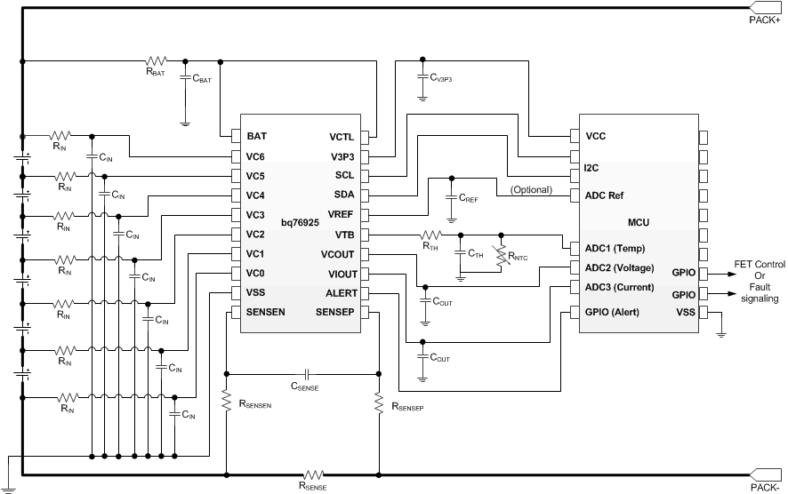
bq76925 typ_sch_lusam9.gif Figure 16. Typical Schematic

9.2.1 Design Requirements

For this design example, use the parameters listed in Table 27.

Table 27. Design Parameters

PARAMETER MIN TYP MAX UNIT
RBAT BAT filter resistance 100 Ω
CBAT BAT filter capacitance 10 µF
RIN External cell input resistance (1) 100 Ω
CIN External cell input capacitance 0.1 1 10 µF
RSENSEN
RSENSEP
Current sense input filter resistance 1K Ω
CSENSE Current sense input filter capacitance 0.1 µF
RVCTL VCTL pullup resistance Without external bypass transistor 0 Ω
With external bypass transistor 200K
CV3P3 V3P3 output capacitance Without external bypass transistor 4.7 µF
With external bypass transistor 1.0
CREF VREF output capacitance 1.0 µF
COUT ADC channel output capacitance VCOUT 0.1 µF
VIOUT 470 2000 pF
(1) RIN,MIN = 0.5 × (VCnMAX / 50 mA) if cell balancing used so that maximum recommended cell balancing current is not exceeded.

9.2.2 Detailed Design Procedure

The following is the detailed design procedure.

  1. Select a proper MCU to complete the battery management solution. Refer to the bq76925 Application report, SLUA619 on MCU requirement.
  2. Based on the system design, determine if an alternative cell connection for 4-series and 5- series battery pack is needed. Refer to the “Cell Amplifier Headroom Under BAT Voltage Drop” section of this document.
  3. Determine if a hold-up circuit for BAT and/or an external bypass transistor is needed based on the system design. Follow the reference schematic to complete the circuit design.
  4. An example circuit design and MCU code implementation is documented in SLUA707 using bq79625 and MSP430G2xx2.

9.2.3 Application Curves

bq76925 voltregwintfet.png
Load step = 3.7 mA
Figure 17. Voltage Regulator With Internal FET
bq76925 Vcout_Settling_200mV_Step.png
Figure 19. VCOUT Settling With 200 mV Step
bq76925 votregwextfet.png
Load step = 40.4 mA
Figure 18. Voltage Regulator With External FET
bq76925 vi_out_settling_200mv_step.png
Figure 20. VIOUT Settling With 200 mV Step

10 Power Supply Recommendations

The maximum operating voltage on the BAT is 26.4 V. In some cases, a peak transient can be more than twice the battery’s DC voltage. Ensure the device does not go beyond its absolute maximum rating.

11 Layout

11.1 Layout Guidelines

  1. Place input filters for BAT, VCx, and SENSEN/P close to the device
  2. Place output capacitors on V3P3, VREF, VCOUT, and VIOUT close to the device
  3. Please output filters (if any) close to the target device (for example, the MCU ADC input ports)
  4. Isolate high-current and low-current groundings. The AFE, filter capacitors, and MCU grounds should connect to the low-current ground plane of the PCB.

11.2 Layout Example

bq76925 layout_filter_place_lusam9.gif Figure 21. Filters and Bypass Capacitors Placement
bq76925 layout_sep_gr_lusam9.gif Figure 22. Separate High-Current and Low-Current Grounds

12 器件和文档支持

12.1 文档支持

12.1.1 相关文档

  • 《半导体和 IC 封装热指标》,SPRA953
  • 《bq76925 入门》,SLUA619
  • 《基于 bq76925 + MSP430G2xx2 的 3 至 6 节电池管理系统》,SLUA707

12.2 接收文档更新通知

如需接收文档更新通知,请访问 www.ti.com.cn 网站上的器件产品文件夹。点击右上角的提醒我 (Alert me) 注册后,即可每周定期收到已更改的产品信息。有关更改的详细信息,请查阅已修订文档中包含的修订历史记录。

12.3 社区资源

The following links connect to TI community resources. Linked contents are provided "AS IS" by the respective contributors. They do not constitute TI specifications and do not necessarily reflect TI's views; see TI's Terms of Use.

    TI E2E™ Online Community TI's Engineer-to-Engineer (E2E) Community. Created to foster collaboration among engineers. At e2e.ti.com, you can ask questions, share knowledge, explore ideas and help solve problems with fellow engineers.
    Design Support TI's Design Support Quickly find helpful E2E forums along with design support tools and contact information for technical support.

12.4 商标

E2E is a trademark of Texas Instruments.

All other trademarks are the property of their respective owners.

12.5 静电放电警告

esds-image

这些装置包含有限的内置 ESD 保护。 存储或装卸时,应将导线一起截短或将装置放置于导电泡棉中,以防止 MOS 门极遭受静电损伤。

12.6 Glossary

SLYZ022 — TI Glossary.

This glossary lists and explains terms, acronyms, and definitions.


Texas Instruments

© Copyright 1995-2025 Texas Instruments Incorporated. All rights reserved.
Submit documentation feedback | IMPORTANT NOTICE | Trademarks | Privacy policy | Cookie policy | Terms of use | Terms of sale