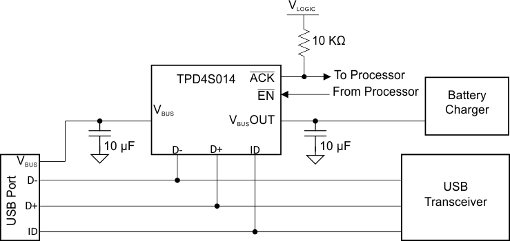
TPD4S014 是一款用于 USB 充电器端口保护的单芯片解决方案。该器件为 D+、D- 提供低电容瞬态电压抑制器 (TVS) 静电放电 (ESD) 钳位并为 ID 引脚提供标准电容。该器件在 VBUS 引脚提供直流电压高达 28V 的过压保护 (OVP)。过压锁定功能可确保当 VBUS 线路出现故障情况时,TPD4S014 能够隔离 VBUS 线路,从而避免内部电路受损。VBUS 升至欠压锁定 (UVLO) 阈值后存在 17ms 开机延迟,从而在 nFET 导通前使电压趋于稳定。该功能可去除毛刺脉冲并避免因线路连接过程中出现的任何振铃问题导致意外开关。
器件型号 | 封装 | 封装尺寸(标称值) |
---|---|---|
TPD4S014 | WSON (10) | 2.00mm x 2.00mm |
Changes from F Revision (September 2015) to G Revision
Changes from E Revision (June 2014) to F Revision
Changes from D Revision (April 2014) to E Revision
Changes from C Revision (December 2011) to D Revision
Changes from B Revision (October 2011) to C Revision
Changes from A Revision (June 2011) to B Revision
PIN | TYPE | DESCRIPTION | |
---|---|---|---|
NAME | NO. | ||
VBUSOUT | 1, 2 | Power Output | Connect to PCB internal PCB plane |
EN | 3 | IO | Enable Active-Low Input. Drive EN low to enable the switch. Drive EN high to disable the switch. |
ACK | 4 | I | Open-Drain Adapter-Voltage Indicator Output. ACK is driven low after the VIN voltage is stable between UVLO and OVLO for 17 ms (typ). Connect a pullup resistor from ACK to the logic I/O voltage of the host system. |
ID | 5 | IO | ESD-protected line |
D– | 6 | IO | ESD-protected line |
D+ | 7 | IO | ESD-protected line |
GND | 8 | Ground | Ground |
VBUS | 9, 10 | USB Input Power | Connector Side of VBUS |
Central PAD | Central PAD | Heat Sink | Electrically disconnected. Use as heat sink. Connect to GND plane via large PCB PAD |
VALUE | UNIT | ||||
---|---|---|---|---|---|
V(ESD) | Electrostatic discharge | Human-body model (HBM), per ANSI/ESDA/JEDEC JS-001(1) | ±2000 | V | |
Charged-device model (CDM), per JEDEC specification JESD22-C101(2) | ±1000 | ||||
IEC 61000-4-2 Contact Discharge | D+, D–, ID, VBUS pins | ±1500 | |||
IEC 61000-4-2 Air-gap Discharge | D+, D–, ID, VBUS pins | ±1500 |
MIN | NOM | MAX | UNIT | |||
---|---|---|---|---|---|---|
TA | Operating free-air temperature | –40 | 85 | °C | ||
VI | Input voltage | VBUSOUT | –0.1 | 5.5 | V | |
VBUS | –0.1 | 5.5 | ||||
EN | –0.1 | 5.5 | ||||
ACK | –0.1 | 5.5 | ||||
D+, D-, ID, | –0.1 | 5.5 | ||||
IVBUS | VBUS continuous current(1) | VBUSOUT | 2.0 | A | ||
CVBUS | Capacitance on VBUS | VBUS Pin | 10 | µF | ||
CVBUSOUT | Capacitance on VBUSOUT | VBUSOUT Pin | 10 | µF | ||
RACK | Pullup resistor on ACK | ACK Pin | 10 | kΩ |
THERMAL METRIC(1) | TPD4S014 | UNIT | |
---|---|---|---|
DSQ (WSON) | |||
8 PINS | |||
RθJA | Junction-to-ambient thermal resistance | 70.3 | °C/W |
RθJCtop | Junction-to-case (top) thermal resistance | 46.3 | °C/W |
RθJB | Junction-to-board thermal resistance | 33.8 | °C/W |
ψJT | Junction-to-top characterization parameter | 2.9 | °C/W |
ψJB | Junction-to-board characterization parameter | 33.5 | °C/W |
RθJCbot | Junction-to-case (bottom) thermal resistance | 16.3 | °C/W |
PARAMETER | TEST CONDITIONS | MIN | TYP | MAX | UNIT | |
---|---|---|---|---|---|---|
IVBUS | VBUS Operating Current Consumption | No load on VBUS_OUT pin, VBUS = 5 V, EN = 0 V |
147.6 | 160 | µA | |
IVBUS_OFF | VBUS Operating Current Consumption | No load on VBUS_OUT pin, VBUS = 5 V, EN = 5 V |
111.8 | 120 | µA |
PARAMETER | TEST CONDITIONS | MIN | TYP | MAX | UNIT | |
---|---|---|---|---|---|---|
TSHDN | Thermal Shutdown | 144 | °C | |||
TSHDN-HYS | Thermal-Shutdown Hysteresis | 23 | °C |
The TPD4S014 provides a single-chip protection solution for USB charger interfaces. The VBUS line is tolerant up to 28 V DC. A Low RON nFET switch is used to disconnect the downstream circuits in case of a fault condition. At power-up, when the voltage on VBUS is rising, the switch will close 17 ms after the input crosses the under voltage threshold, thereby making power available to the downstream circuits. The TPD4S014 also has an ACK output, which de-asserts to alert the system a fault has occurred. The TPD4S014 offers 4 channel ESD clamps for D+, D-, ID, and VBUS pins that provide IEC61000-4-2 level 4 ESD protection. This eliminates the need for external TVS clamp circuits in the application.
When the input voltage rises above VOVP, or drops below the VUVLO, the internal VBUS switch is turned off, removing power to the application. The ACK signal is de-asserted when a fault condition is detected. If the fault was an over voltage event, the VBUS nFET switch turns on 8 ms (tREC) after the input voltage returns below VOVP – VHYS_OVP and remains above VUVLO. If the fault was an under voltage event, the switch turns on 17 ms after the voltage returns above VUVLO+ (similar to start up). When the switch turns on, the ACK is asserted once again.
The nFET switch has a total on resistance (RON) of 151 mΩ. This equates to a voltage drop of 302 mV when charging at the maximum 2.0 A current level. Such low RON helps provide maximum potential to the system as provided by an external charger.
The D+, D–, ID, and VBUS pins can withstand ESD events up to ±15-kV contact and air-gap. An ESD clamp diverts the current to ground.
The over voltage and under voltage lockout feature ensures that if there is a fault condition at the VBUS line, the TPD4S014 is able to isolate the VBUS line and protect the internal circuitry from damage. Due to the body diode of the nFET switch, if there is a short to ground on VBUS the system is expected to limit the current to VBUSOUT.
The D+/D– ESD protection pins have low capacitance so there is no significant impact to the signal integrity of the USB 2.0 Hi-Speed data rate.
Upon startup, TPD4S014 has a built in startup delay. An internal oscillator controls a charge pump to control the turn-on delay (tON) of the internal nFET switch. The internal oscillator controls the timers that enable the turn-on of the charge pump and sets the state of the open-drain ACK output. If VBUS < VUVLO or if VBUS > VOVLO, the internal oscillator remains off, thus disabling the charge pump. At any time, if VBUS drops below VUVLO or rises above VOVLO, ACK is released and the nFET switch is disabled.
A 17 ms deglitch time has been introduced into the turn on sequence to ensure that the input supply has stabilized before turning the nFET switch ON. Noise on the VBUS line could turn ON the nFET switch when the fault condition is still active. To avoid this, OVP glitch immunity allows noise on the VBUS line to be rejected. Such a glitch protection circuitry is also introduced in the turn off sequence in order to prevent the switch from turning off for voltage transients. The glitch protection circuitry integrates the glitch over time, allowing the OVP circuitry to trigger faster for larger voltage excursions above the OVP threshold and slower for shorter excursions.
External control of the nFET switch is provided by an active low EN pin. An ACK pin provides output logic to acknowledge VBUS is between UVLO and OVP by asserting low.
When the device is ON, current flowing through the device will cause the device to heat up. Overheating can lead to permanent damage to the device. To prevent this, an over temperature protection has been designed into the device. Whenever the junction temperature exceeds 145ºC, the switch will turn off, thereby limiting the temperature. The ACK signal will be asserted for an over temperature event. Once the device cools down to below 120ºC the ACK signal will be de-asserted, and the switch will turn on if the EN is active and the VBUS voltage is within the UVLO and OVP thresholds. While the over temperature protection in the device will not kick-in unless the die temperature reaches 145ºC, it is generally recommended that care is taken to keep the junction temperature below 125 ºC. Operation of the device above 125 ºC for extended periods of time can affect the long-term reliability of the part.
The junction temperature of the device can be calculated using below formula:
where
where
Example
At 2-A continuous current power dissipation is given by:
If the ambient temperature is about 60°C the junction temperature will be:
This implies that, at an ambient temperature of 60ºC, TPD4S014 can pass a continuous 2 A without sustaining damage. Conversely, the above calculation can also be used to calculate the total continuous current the TPD4S014 can handle at any given temperature.
Table 1 is the function table for TPD4S014.
OTP | UVLO | OVLO | EN | SW | ACK |
---|---|---|---|---|---|
X | H | X | X | OFF | H |
X | X | H | X | OFF | H |
L | L | L | H | OFF | L |
L | L | L | L | ON | L |
H | X | X | X | OFF | H |
OTP = | Over temperature protection circuit active |
UVLO = | Under voltage lock-out circuit active |
OVLO = | Over voltage lock-out circuit active |
SW = | Load switch |
CP = | Charge pump |
X = | Don’t Care |
H = | True |
L = | False |
NOTE
Information in the following applications sections is not part of the TI component specification, and TI does not warrant its accuracy or completeness. TI’s customers are responsible for determining suitability of components for their purposes. Customers should validate and test their design implementation to confirm system functionality.
The TPD4S014 is a single-chip solution for USB charger port protection. This device offers low capacitance TVS type ESD clamps for the D+, D–, and standard capacitance for the ID pin. On the VBUS pin, this device can handle over voltage protection up to 28 V. The over voltage lockout feature ensures that if there is a fault condition at the VBUS line TPD4S014 is able to isolate the VBUS line and protect the internal circuitry from damage. In order to let the voltage stabilize before closing the switch there is a 17 ms turn on delay after VBUS crosses the UVLO threshold. This function acts as a de-glitch which prevents unnecessary switching if there is any ringing on the line during connection. Due to the body diode of the nFET switch, if there is a short to ground on VBUS the system is expected to limit the current to VBUSOUT.
Table 2 shows the design parameters.
DESIGN PARAMETERS | EXAMPLE VALUE |
---|---|
Signal range on VBUS | 3.3 V – 5.9 V |
Signal range on VBUSOUT | 3.9 V – 5.9 V |
Signal range on D+/D– and ID | 0 V – 5 V |
Drive EN low (enabled) | 0 V – 0.5 V |
Drive EN high (disabled) | 1 V – 6 V |
To begin the design process, some parameters must be decided upon. The designer needs to know the following:
Table 3 shows the design parameters.
DESIGN PARAMETERS | EXAMPLE VALUE |
---|---|
Signal range on VBUS | 3.3 V – 5.9 V |
Signal range on VBUSOUT | 3.9 V – 5.9 V |
Signal range on D+/D– and ID | 0 V – 5 V |
Drive EN low (enabled) | 0 V – 0.5 V |
Drive EN high (disabled) | 1 V – 6 V |
To begin the design process, some parameters must be decided upon. The designer needs to know the following:
Refer to Application Curves in the previous section.
TPD4S014 Is designed to receive power from a USB 3.0 (or lower) VBUS source. It can operate normally (nFET ON) between 3.0 V and 5.9 V. Thus, the power supply (with a ripple of VRIPPLE) requirement for TPD4S014 to be able to switch the nFET ON is between 3.0 V + VRIPPLE and 5.9 V – VRIPPLE.
When designing layout for TPD4S014, note that VBUSOUT and VBUS pins allow for extra wide traces for good power delivery. In the example shown, these pins are routed with 25 mil (0.64 mm) wide traces. Place the VBUSOUT and VBUS capacitors as close to the device pins as possible. Pull ACK up to the Processor logic level high with a resistor. Use external and internal ground planes and stitch them together with VIAs as close to the GND pins of TPD4S014 as possible. This allows for a low impedance path to ground so that the device can properly dissipate any ESD events.
The following links connect to TI community resources. Linked contents are provided "AS IS" by the respective contributors. They do not constitute TI specifications and do not necessarily reflect TI's views; see TI's Terms of Use.
E2E is a trademark of Texas Instruments.
All other trademarks are the property of their respective owners.
这些装置包含有限的内置 ESD 保护。 存储或装卸时,应将导线一起截短或将装置放置于导电泡棉中,以防止 MOS 门极遭受静电损伤。
SLYZ022 — TI Glossary.
This glossary lists and explains terms, acronyms, and definitions.
以下页中包括机械、封装和可订购信息。这些信息是针对指定器件可提供的最新数据。这些数据会在无通知且不对本文档进行修订的情况下发生改变。欲获得该数据表的浏览器版本,请查阅左侧的导航栏。
德州仪器(TI) 及其下属子公司有权根据 JESD46 最新标准, 对所提供的产品和服务进行更正、修改、增强、改进或其它更改, 并有权根据 JESD48最新标准中止提供任何产品和服务。客户在下订单前应获取最新的相关信息, 并验证这些信息是否完整且是最新的。所有产品的销售都遵循在订单确认时所提供的TI 销售条款与条件。
TI 保证其所销售的组件的性能符合产品销售时 TI 半导体产品销售条件与条款的适用规范。仅在 TI 保证的范围内,且 TI 认为有必要时才会使用测试或其它质量控制技术。除非适用法律做出了硬性规定,否则没有必要对每种组件的所有参数进行测试。
TI 对应用帮助或客户产品设计不承担任何义务。客户应对其使用 TI 组件的产品和应用自行负责。为尽量减小与客户产品和应用相关的风险,客户应提供充分的设计与操作安全措施。
TI 不对任何 TI 专利权、版权、屏蔽作品权或其它与使用了 TI 组件或服务的组合设备、机器或流程相关的 TI 知识产权中授予 的直接或隐含权限作出任何保证或解释。TI所发布的与第三方产品或服务有关的信息,不能构成从 TI 获得使用这些产品或服 务的许可、授权、或认可。使用此类信息可能需要获得第三方的专利权或其它知识产权方面的许可,或是 TI 的专利权或其它知识产权方面的许可。
对于 TI 的产品手册或数据表中 TI 信息的重要部分,仅在没有对内容进行任何篡改且带有相关授权、条件、限制和声明的情况 下才允许进行复制。TI 对此类篡改过的文件不承担任何责任或义务。复制第三方的信息可能需要服从额外的限制条件。
在转售 TI 组件或服务时,如果对该组件或服务参数的陈述与 TI 标明的参数相比存在差异或虚假成分,则会失去相关 TI 组件或服务的所有明示或暗示授权,且这是不正当的、欺诈性商业行为。TI 对任何此类虚假陈述均不承担任何责任或义务。
客户认可并同意,尽管任何应用相关信息或支持仍可能由 TI 提供,但他们将独力负责满足与其产品及在其应用中使用 TI 产品相关的所有法律、法规和安全相关要求。客户声明并同意,他们具备制定与实施安全措施所需的全部专业技术和知识,可预见故障的危险后果、监测故障及其后果、降低有可能造成人身伤害的故障的发生机率并采取适当的补救措施。客户将全额赔偿因 在此类安全关键应用中使用任何 TI 组件而对 TI及其代理造成的任何损失。
在某些场合中,为了推进安全相关应用有可能对 TI 组件进行特别的促销。TI 的目标是利用此类组件帮助客户设计和创立其特有的可满足适用的功能安全性标准和要求的终端产品解决方案。尽管如此,此类组件仍然服从这些条款。
TI 组件未获得用于 FDA Class III(或类似的生命攸关医疗设备)的授权许可,除非各方授权官员已经达成了专门管控此类使 用的特别协议。
只有那些 TI 特别注明属于军用等级或“增强型塑料”的 TI 组件才是设计或专门用于军事/航空应用或环境的。购买者认可并同 意,对并非指定面向军事或航空航天用途的 TI组件进行军事或航空航天方面的应用,其风险由客户单独承担,并且由客户独 力负责满足与此类使用相关的所有法律和法规要求。
TI 已明确指定符合 ISO/TS16949 要求的产品,这些产品主要用于汽车。在任何情况下,因使用非指定产品而无法达到 ISO/TS16949要求,TI不承担任何责任。
德州仪器在线技术支持社区: www.deyisupport.com
邮寄地址: 上海市浦东新区世纪大道1568 号,中建大厦32 楼邮政编码: 200122
Copyright© 2016, 德州仪器半导体技术(上海)有限公司