SLVA934A November 2017 – May 2020 TPS2660
4 Suggested Fault Handling Methods
Generally, ESD structures of MCUs or DC/DC converters can take 60 mA of current for a short period during their operating life without degradation in performance. However, if the ESD structures are not able to handle 60 mA of current during a faulty reverse input supply, the current through FLTb needs to be limited by external means.
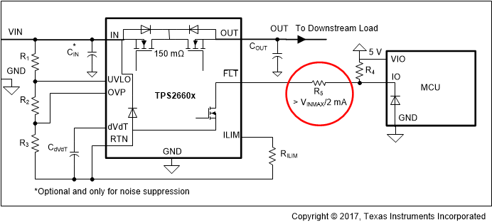
Adding a current limit resistance of R5 > VINMAX/2 mA between FLTb and IO of MCU as shown in Figure 5 limits current through ESD structure to be less than 2 mA. R5 can be chosen so that current through the ESD structure is less than the absolute maximum ratings of the IO pin of the MCU or the enable pin of the DC/DC converter, and current through the FLTb pin of the TPS2660 is always less than its absolute maximum rating of 10 mA.
 Figure 5. Proposed System Fix With Series Current Limiting Resistor
 Sometimes it is not feasible to place a resistor in series to FLTb. Consider the system shown in Figure 1 where FLTb signal provides power good indication to the DC/DC converter. Pullup and pulldown resistors R4 and R5 must be scaled up if a 40-kΩ resistor is added in series to FLTb. For example, on a 24-V power supply application with a range of 18 V to 36 V, R4 and R5 are 70 kΩ and 5 kΩ, respectively, for 1.23 V of an enable threshold and 0.5 V of a shutdown threshold. Now with a 40-kΩ series in place to limit current through FLTb, R4 and R5 must be scaled to 2.8 MΩ and 200 kΩ, respectively, to meet both the enable and shutdown thresholds. This scaling is not always possible because the current through R4 and R5 are 12 µA at maximum and can become comparable to a leakage current > 1 µA of the enable pin of DC/DC converter. Furthermore, a shift in the threshold across temperature can be very wide due to the variation of leakage current over temperature.
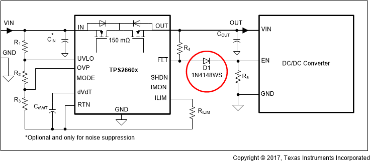
In this case, it is recommended to place D1, a 60-V rated blocking diode like 1N4148WS as shown in Figure 6, to block the current through FLTb and modify R4 and R5 to accommodate for the forward drop of D1.
 Figure 6. Proposed System Fix With Blocking Diode