SLVA654B June 2014 – March 2019 DRV8301 , DRV8301-Q1 , DRV8302 , DRV8303 , DRV8307 , DRV8308 , DRV8312 , DRV8323R , DRV8332
-
Hardware design considerations for an efficient vacuum cleaner using a BLDC motor
- Trademarks
- 1 Suction Principle
- 2 Brushless DC Motors (BLDC)
- 3 Microcontrollers
- 4 Gate Driver and MOSFETs
- 5 Isolation
- 6 Power Management (6 to 60-V DC Power Supply)
- 7 CAP and QEP interfaces
- 8 Enhanced Controller Area Network (eCAN)
- 9 High-Resolution and Synchronized ADCs
- 10 DRV8323R
- 11 Feedback Stage
- 12 Conclusion
- 13 About the Author
- 14 References
- Revision History
2.2.1.2.1 Sensorless Control: Using Zero Crossing of the Back EMF Signal
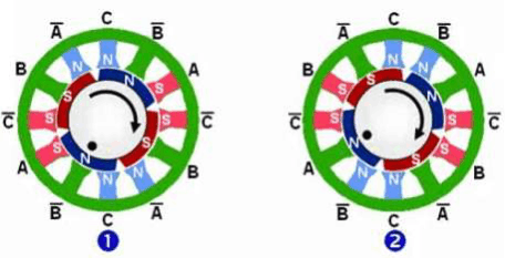
Rotor-position detection occurs by using one of the two previously-mentioned methods. Figure 5 shows the process of commutation. The 3-phase BLDC motor has been split into 12 stator poles as shown in Figure 5. Phase winding energizes such that a positive current creates a south pole at A and A bar has a north pole. Similarly C has a north pole and then C bar has a south pole. Commutation can begin when the rotor position is determined. When the rotor begins to move the south pole of the rotor enters the region of the stator where the north pole exists. The sensor detects this movement, and before the rotor can reach the north pole (region under the phase A), phase A is turned off because the rotor has entered a new commutation zone. Phase B then turns on. The magnetic pattern on the stator is advanced by 30 degrees. The rotor must move further in order to reach the north pole as shown in Figure 5(2). As the rotor travels toward the north pole, it crosses a new commutation zone and the process continues on. There are six stator commutation states and depending on the rotor position, the respective commutation state can be applied.
 Figure 5. Commutation Process