SLOA329 August 2022 TAS2781
4 Dynamic Range Compressor (DRC)
The dynamic range of an audio signal is the ratio of the loudest signal to the quietest signal. For a loudspeaker, the rated power and the peak excursion restricts the maximum output signal and the noise floor determines the minimum output signal. As a result, it is necessary to apply controls in a signal processor to adjust the level of the audio signal to match the dynamic range of the loudspeaker. Typically, the dynamic range of the loudspeaker is limited and hence there is a compression (or overall reduction) of dynamic range. To increase the loudness, dynamic range compressors further reduce the dynamic range by amplifying soft signals.
Dynamic range compressors alter the audio signal based on frequency content and signal level. The compressors have a gain control element in the main signal path and a side-chain containing a detector and a gain computer. The detector tracks the signal level and the gain computer alters the gain of the main signal path based on the signal level. The side-chain activity is governed by five primary parameters – threshold, offset, ratio, attack, and release. If the signal level is above the threshold, the gain is altered using the ratio and offset parameter. The ratio determines the slope while the offset determines the starting point for the gain when the signal level is above the threshold. The alteration of gain is controlled in time using attack and release controls. The slope is the inverse of the ratio parameter.
A compressor reduces the dynamic range by turning down the loudest signal dynamically, that is, the compressor makes loud sounds quieter. The compressor achieves this by making the increase in signal levels smaller by reducing the gain for signals above the threshold. The ratio parameter for the compressor is always greater than 1 (that is, slope < 1).
 Figure 4-2 Compressor
Conversely, an expander increases the dynamic range of the signal passing through and the expander makes quiet parts of sound quieter. The expander achieves this by making the reduction of signal levels larger by reducing the gain for signals below the threshold. The most common use of the expander is noise reduction – as the sound becomes quieter and closer to the noise floor, the expander reduces the signal further resulting in an improvement in noise reduction. The ratio parameter for the expander is always less than 1 (that is, slope > 1).
 Figure 4-3 Expander
 Typically, signals are expanded at low levels (to reduce noise) but compressed at high levels (to prevent amplifier clipping).
The dynamic range compressor also supports a noise-gate feature. Unlike the expander, the noise-gate applies a fixed gain (that is, attenuation) to the audio signal when the signal is below a certain threshold. This is over and above the typical expansion gain applied for low signal levels. The noise gate is typically used to remove background noise between louder sounds.
The threshold is the beginning of gain adjustment. When the input is below the threshold for compressors, or above the threshold for expanders, typically the dynamic processor does not engage. When the input is above the threshold (compression) or below the threshold (expansion), the side-chain asserts itself and reduces the volume.
The detector threshold is RMS energy based. RMS energy-based detectors maintain dynamic range based on the power handling capability of the loudspeaker. An averaging time constant is used to determine RMS of the input signal. This is known as the energy time constant.
 Figure 4-5 Example DRC Plot
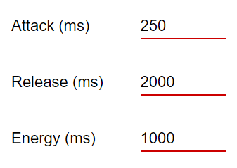
 The time required for the compressor to react to an increase in side-chain input level above the threshold is called the attack, that is, this defines how quickly the gain is turned down. Conversely, when the side-chain input level falls below the threshold, the time taken to turn the gain back up is called release. Both attack and release are defined by a time constant resulting in a constant dB-per-second gain change at the output.
 Figure 4-6 Time Constant Controls
 There are three dynamic range compressors available – each can be programmed to cover a certain audio frequency range. The three dynamic compressors (known as the 3-band DRC), each independently programmable, covers the entire audio range from 20 Hz to 20 kHz using a three-band linked crossover network. These DRCs use an RMS-based detector.
 Figure 4-8 3-Band DRC
 Each compressor has three regions for signal-level control – low-signal region, mid-signal region ,and high-signal region – with the threshold, offset, and ratio (compression or expansion) for each region being programmed. The attack and release are the same across all regions. The side-chain input level is compared with each threshold to determine the signal region and accordingly the ratio, is used by the gain computer to apply the gain in the main signal path.