SLLA498 October 2020
4.2 Phase-shifted Full Bridge (PSFB)
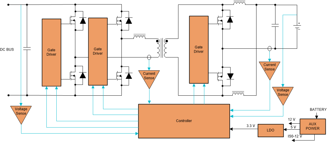
Figure 4-2 illustrates the basic topology of the Phase-Shifted Full-Bridge converter. The PSFB topology is similar to a hard-switched full bridge except the way the active switches are driven – even though it is a PWM-controlled topology, all the switches are driven with 50% duty cycle PWMs. This topology allows only unidirectional power transfer. It is a modular topology and hence can be scaled to higher power levels.
 Figure 4-2 Phase-shifted Full-Bridge Topology.
 The power transfer between the primary and secondary is controlled by varying the phase between the switch legs of the primary side bridge. With proper control, it is possible to obtain ZVS turn on of one leg and low voltage turn on of the other leg, thus minimizing losses. The diodes on the secondary can experience hard switching, resulting in more losses which can reduce the efficiency of this converter. This converter suffers non-ZVS turn-on and turn-off at light load conditions. Because of this, burst mode operation is typically used to maintain ZVS at light load conditions. Frequency dithering can be easily implemented to reduce the conducted EMI signature in this topology. A DC blocking capacitor to block DC voltage offset saturating the transformer in voltage mode control and an additional shim inductor to tune ZVS operation are required, making the converter bulky.
For more detailed analysis of this topology, see the Phase-Shifted Full Bridge DC/DC Power Converter Design Guide. TI's Phase-Shifted Full Bridge DC/DC Power Converter reference design explains the implementation of this topology in a typical application. This topology being a unidirectional DC/DC topology is an option to consider for the DC/DC stage (see Figure 3-1) between the solar panels and HV DC Bus.