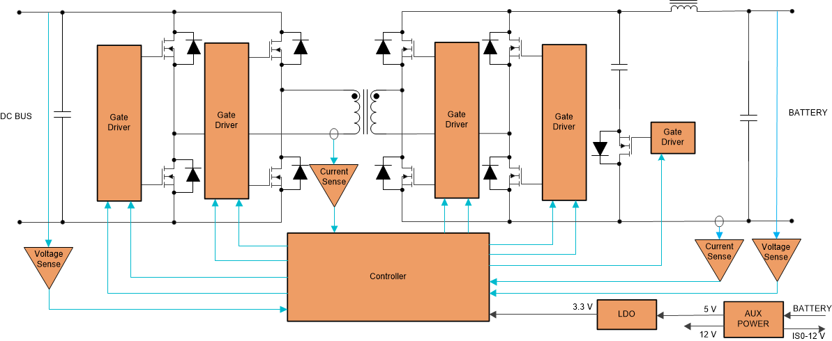
The Active clamped current-fed bridge converter shown in Figure 4-6 is another bidirectional power conversion topology commonly used in low voltage (48 V and lower) battery storage systems. Some lower power systems use a push-pull power stage on the battery side instead of the full bridge. This power stage works as a phase shifted full bridge while charging the battery from the DC bus and as an isolated boost converter (with active clamp) while discharging the battery to the DC bus.
While charging the battery, phase shift control is used similar to the PSFB circuit discussed earlier. With sufficient leakage inductance in the transformer, the circuit can achieve ZVS on the HV and LV side MOSFETs. While discharging battery, the circuit transforms to a current-fed bridge topology, which is nothing but an isolated boost converter. To achieve ZVS, an active clamp circuit consisting of a capacitor and a MOSFET is used. Simple fixed frequency duty cycle control is used in this mode. The simple control method is the biggest advantage of this topology - fixed frequency phase shift control while charging and fixed frequency duty cycle control while discharging. Soft switching is achieved without much effort in either direction. Low di/dt on the HV side MOSFETs allows the use of Silicon devices (with relatively faster body diodes), reducing system cost. However, the conduction losses are higher due to the relatively large clamp circuit current, reducing the efficiency somewhat. It will also need low power start-up winding on the boost inductor for safe start-up. Still, it is considered to be a lower cost option for the bidirectional DC/DC stage (see
Figure 3-1) between the Battery Management System and HV DC Bus.
The TI reference design 2kW, 48V to 400V, >93% Efficiency, Isolated Bidirectional DC-DC Converter Reference Design for UPS contains details on the implementation of this converter.
 Figure 4-6 Active Clamped Current-fed Bridge Converter.