SLAA833A May 2018 – October 2019 MSP430FR2353 , MSP430FR2355
- How to Use the Smart Analog Combo in MSP430™ MCUs
- Revision History
1.1 Smart Analog Combo (SAC) Concept
The SAC module includes one programmable gain amplifier (PGA) and one 12-bit digital-to-analog converter (DAC). The module can be used for signal conditioning in input path and waveform generation in output path. There are three different configuration levels for the SAC module: SAC-L1, SAC-L2, and SAC-L3.
- SAC-L1 is the minimum feature set and integrates only the operational amplifier.
- SAC-L2 includes the operational amplifier and a feedback resistance ladder to form a PGA with gain up to 33.
- SAC-L3 is the maximum feature set that integrates the SAC-L2 PGA and a 12-bit DAC.
Different MSP430 MCUs have different SAC configuration levels. For example, the MSP430FR2311 integrates one SAC-L1 module, and the MSP430FR2355 integrates four SAC-L3 modules. For the SAC configuration level and quantity on a specific MCU, see the device-specific data sheet.
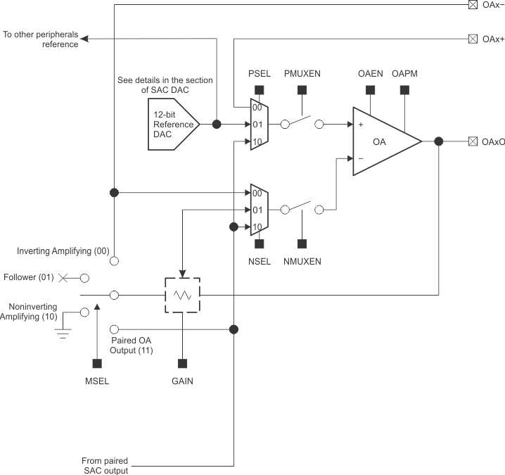
Figure 1 shows the block diagram of SAC-L3 module. The integrated amplifier supports rail-to-rail input and rail-to-rail output. The two internal multiplexers support multiple input selections for the operational amplifier (OA). The op-amp power mode (OAPM) control bit selects the OA power mode. In high-power mode, the OA provides higher gain bandwidth and slew rate. If lower power consumption is more critical in the application, select the OA low-power mode by setting the OAPM bit to 1. The feedback resistance ladder connects the OA output with the negative input as the feedback routing. With the feedback routing, the OA supports both inverting PGA mode and noninverting PGA mode. A 12-bit DAC is also integrated in the SAC-L3 module. The DAC can be used to generate a bias voltage to the OA or can work with OA to drive a waveform output on the pad.
 Figure 1. Smart Analog Combo Block Diagram