• Menu
  • Product
  • Email
  • PDF
  • Order now
  • CDCLVP2106 12-LVPECL Output, High-Performance Clock Buffer

    • SCAS887B September   2009  – January 2016 CDCLVP2106

      PRODUCTION DATA.  

  • CONTENTS
  • SEARCH
  • CDCLVP2106 12-LVPECL Output, High-Performance Clock Buffer
  1. 1 Features
  2. 2 Applications
  3. 3 Description
  4. 4 Revision History
  5. 5 Pin Configuration and Functions
  6. 6 Specifications
    1. 6.1  Absolute Maximum Ratings
    2. 6.2  ESD Ratings
    3. 6.3  Recommended Operating Conditions
    4. 6.4  Thermal Information
    5. 6.5  Electrical Characteristics: LVCMOS Input, at VCC = 2.375 V to 3.6 V
    6. 6.6  Electrical Characteristics: Differential Input, at VCC = 2.375 V to 3.6 V
    7. 6.7  Electrical Characteristics: LVPECL Output, at VCC = 2.375 V to 2.625 V
    8. 6.8  Electrical Characteristics: LVPECL Output, at VCC = 3 V to 3.6 V
    9. 6.9  Timing Requirements, at VCC = 2.375 V to 2.625 V
    10. 6.10 Timing Requirements, at VCC = 3 V to 3.6 V
    11. 6.11 Typical Characteristics
  7. 7 Parameter Measurement Information
    1. 7.1 Test Configurations
  8. 8 Detailed Description
    1. 8.1 Overview
    2. 8.2 Functional Block Diagram
    3. 8.3 Feature Description
    4. 8.4 Device Functional Modes
      1. 8.4.1 LVPECL Output Termination
      2. 8.4.2 Input Termination
  9. 9 Application and Implementation
    1. 9.1 Application Information
    2. 9.2 Typical Application
      1. 9.2.1 Design Requirements
      2. 9.2.2 Detailed Design Procedure
      3. 9.2.3 Application Curves
  10. 10Power Supply Recommendations
    1. 10.1 Power-Supply Filtering
  11. 11Layout
    1. 11.1 Layout Guidelines
    2. 11.2 Layout Example
    3. 11.3 Thermal Considerations
  12. 12Device and Documentation Support
    1. 12.1 Documentation Support
      1. 12.1.1 Related Documentation
    2. 12.2 Community Resources
    3. 12.3 Trademarks
    4. 12.4 Electrostatic Discharge Caution
    5. 12.5 Glossary
  13. 13Mechanical, Packaging, and Orderable Information
  14. IMPORTANT NOTICE
search No matches found.
  • Full reading width
    • Full reading width
    • Comfortable reading width
    • Expanded reading width
  • Card for each section
  • Card with all content


DATA SHEET

CDCLVP2106 12-LVPECL Output, High-Performance Clock Buffer

1 Features

  • Dual 1:6 Differential Buffer
  • Two Clock Inputs
  • Universal Inputs Can Accept LVPECL, LVDS, LVCMOS/LVTTL
  • 12 LVPECL Outputs
  • Maximum Clock Frequency: 2 GHz
  • Maximum Core Current Consumption: 92 mA
  • Very Low Additive Jitter: <100 fs, RMS in 10-kHz to 20-MHz Offset Range
  • 2.375-V to 3.6-V Device Power Supply
  • Maximum Propagation Delay: 550 ps
  • Maximum Within Bank Output Skew: 20 ps
  • LVPECL Reference Voltage, VAC_REF, Available for Capacitive-Coupled Inputs
  • Industrial Temperature Range: –40°C to +85°C
  • Supports 105°C PCB Temperature (Measured with a Thermal Pad)
  • Available in 6-mm × 6-mm, 40-Pin VQFN (RHA) Package
  • ESD Protection Exceeds 2000 V (HBM)

2 Applications

  • Wireless Communications
  • Telecommunications/Networking
  • Medical Imaging
  • Test and Measurement Equipment

3 Description

The CDCLVP2106 is a highly versatile, low additive jitter buffer that can generate 12 copies of LVPECL clock outputs from two LVPECL, LVDS, or LVCMOS inputs for a variety of communication applications. It has a maximum clock frequency up to 2 GHz. Each buffer block consists of one input that feeds two LVPECL outputs. The overall additive jitter performance is less than 0.1 ps, RMS from 10 kHz to 20 MHz, and overall output skew is as low as 20 ps, making the device a perfect choice for use in demanding applications.

The CDCLVP2106 clock buffer distributes two clock inputs (IN0, IN1) to 12 pairs of differential LVPECL clock outputs (OUT0, OUT11) with minimum skew for clock distribution. Each buffer block consists of one input that feeds two LVPECL clock outputs. The inputs can be LVPECL, LVDS, or LVCMOS/LVTTL.

The CDCLVP2106 is specifically designed for driving 50-Ω transmission lines. When driving the inputs in single-ended mode, the LVPECL bias voltage (VAC_REF) should be applied to the unused negative input pin. However, for high-speed performance up to 2 GHz, differential mode is strongly recommended.

The CDCLVP2106 is characterized for operation from –40°C to +85°C and is available in a 6-mm × 6-mm, VQFN-40 package.

Device Information(1)

PART NUMBER PACKAGE BODY SIZE (NOM)
CDCLVP2106 VQFN (40) 6.00 mm × 6.00 mm
  1. For all available packages, see the orderable addendum at the end of the data sheet.

Simplified Schematic
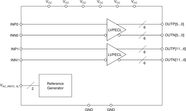
CDCLVP2106 fbd_cas887.gif

4 Revision History

Changes from A Revision (August 2011) to B Revision

  • Added ESD Ratings table, Typical Characteristics section, Detailed Description section, Device Functional Modes section, Application and Implementation section, Power Supply Recommendations section, Layout section, Device and Documentation Support section, and Mechanical, Packaging, and Orderable Information sectionGo
  • Added support for 105ºC thermal pad temperature Go
  • Deleted Device Comparison table; information in POA Go
  • Changed order of Pin Functions table to alphabetical by pin name Go
  • Added VOH specification for TPCB≤ 105ºC in Electrical Characteristics: LVPECL Output, at VCC = 2.375 V to 2.625 V Go
  • Added VOL specification for TPCB≤ 105ºC in Electrical Characteristics: LVPECL Output, at VCC = 2.375 V to 2.625 V Go
  • Added IEE specification for TPCB≤ 105ºC in Electrical Characteristics: LVPECL Output, at VCC = 2.375 V to 2.625 V Go
  • Added ICC specification for TPCB≤ 105ºC in Electrical Characteristics: LVPECL Output, at VCC = 2.375 V to 2.625 V Go
  • Added VOH specification for TPCB≤ 105ºC in Electrical Characteristics: LVPECL Output, at VCC = 3 V to 3.6 V Go
  • Added VOL specification for TPCB≤ 105ºC in Electrical Characteristics: LVPECL Output, at VCC = 3 V to 3.6 V Go
  • Added IEE specification for TPCB≤ 105ºC in Electrical Characteristics: LVPECL Output, at VCC = 3 V to 3.6 V Go
  • Added ICC specification for TPCB≤ 105ºC in Electrical Characteristics: LVPECL Output, at VCC = 3 V to 3.6 V Go
  • Added Footnote "100 MHz Wenzel oscillator, Input slew rate = 0.9 V/ns (single-ended)."Go
  • Added tRJIT for f OUT = 100 MHz, Input AC coupled, VICM = VAC_REF, 12 kHz to 20 MHz Go
  • Added tRJIT for fOUT = 122.88 MHz, Input AC coupled, VICM = VAC_REF, 12 kHz to 20 MHz Go
  • Added tRJIT for fOUT = 156.25 MHz, Input AC coupled, VICM = VAC_REF, 12 kHz to 20 MHz Go
  • Added tRJIT for fOUT = 312.5 MHz, Input AC coupled, VICM = VAC_REF, 12 kHz to 20 MHz Go

Changes from * Revision (September 2009) to A Revision

  • Revised descriptions of pins 7 and 4Go
  • Corrected VIL parameter description in Electrical Characteristics table for LVCMOS inputGo
  • Added footnote (2) to Electrical Characteristics table for LVPECL Output, VCC = 2.375 V to 2.625 VGo
  • Changed recommended resistor values in Figure 12(a)Go
  • Changed recommended resistor values in Figure 16Go

5 Pin Configuration and Functions

RHA Package
40-Pin VQFN
Top View
CDCLVP2106 po_cas887.gif
1. Thermal pad must be soldered to ground.

Pin Functions

PIN I/O DESCRIPTION
NAME NO.
GND1, GND2 21, 30 Ground Device grounds
INP0, INN0 9, 8 Input Differential input pair or single-ended input no. 0
INP1, INN1 2, 3 Input Differential input pair or single-ended input no. 1
OUTP0 OUTN0 12, 13 Output Differential LVPECL output pair no. 0
OUTP1, OUTN1 14, 15 Output Differential LVPECL output pair no. 1
OUTP2, OUTN2 16, 17 Output Differential LVPECL output pair no. 2
OUTP3, OUTN3 18, 19 Output Differential LVPECL output pair no. 3
OUTP4, OUTN4 22, 23 Output Differential LVPECL output pair no. 4
OUTP5, OUTN5 24, 25 Output Differential LVPECL output pair no. 5
OUTP6, OUTN6 26, 27 Output Differential LVPECL output pair no. 6
OUTP7, OUTN7 28, 29 Output Differential LVPECL output pair no. 7
OUTP8, OUTN8 32, 33 Output Differential LVPECL output pair no. 8
OUTP9, OUTN9 34, 35 Output Differential LVPECL output pair no. 9
OUTP10, OUTN10 36, 37 Output Differential LVPECL output pair no. 10
OUTP11, OUTN11 38, 39 Output Differential LVPECL output pair no. 11
VAC_REF0 7 Output Bias voltage output for capacitive coupled input pair no. 0. Do not use VAC_REF at VCC < 3 V. If used, TI recommends a 0.1-μF capacitor to GND on this pin. The output current is limited to 2 mA.
VAC_REF1 4 Output Bias voltage output for capacitive coupled input pair no. 1. Do not use VAC_REF at VCC < 3 V. If used, TI recommends using a 0.1-μF capacitor to GND on this pin. The output current is limited to 2 mA.
VCC 5, 6, 11, 20, 31, 40 Power 2.5-V or 3.3-V supplies for the device
NC 1, 10 — Do not connect

6 Specifications

6.1 Absolute Maximum Ratings

over operating free-air temperature range (unless otherwise noted)(1)
MIN MAX UNIT
VCC Supply voltage(2) –0.5 4.6 V
VIN Input voltage(3) –0.5 VCC + 0.5 V
VOUT Output voltage(3) –0.5 VCC + 0.5 V
IIN Input current 20 mA
IOUT Output current 50 mA
TA Specified free-air temperature (no airflow) –40 85 °C
TJ Maximum junction temperature 125 °C
Tstg Storage temperature –65 150 °C
(1) Stresses beyond those listed under Absolute Maximum Ratings may cause permanent damage to the device. These are stress ratings only, which do not imply functional operation of the device at these or any other conditions beyond those indicated under Recommended Operating Conditions. Exposure to absolute-maximum-rated conditions for extended periods may affect device reliability.
(2) All supply voltages must be supplied simultaneously.
(3) The input and output negative voltage ratings may be exceeded if the input clamp-current and output clamp-current ratings are observed.

6.2 ESD Ratings

VALUE UNIT
V(ESD) Electrostatic discharge Human-body model (HBM), per ANSI/ESDA/JEDEC JS-001(1) 2000 V
Charged-device model (CDM), per JEDEC specification JESD22-C101(2) 1000
(1) JEDEC document JEP155 states that 500-V HBM allows safe manufacturing with a standard ESD control process.
(2) JEDEC document JEP157 states that 250-V CDM allows safe manufacturing with a standard ESD control process.

6.3 Recommended Operating Conditions

over operating free-air temperature range (unless otherwise noted).
MIN NOM MAX UNIT
VCC Supply voltage 2.375 2.5/3.3 3.60 V
TA Ambient temperature –40 85 °C
TPCB PCB temperature (measured at thermal pad) 105 °C

6.4 Thermal Information

THERMAL METRIC(1)(2)(3) CDCLVP2106 UNIT
(RHA) VQFN
40 PINS
RθJA Junction-to-ambient thermal resistance(4) 0 LFM 34.7 °C/W
RθJC(top) Junction-to-case (top) thermal resistance 23.7 °C/W
RθJB Junction-to-board thermal resistance 10.1 °C/W
ψJT Junction-to-top characterization parameter 0.5 °C/W
ψJB Junction-to-board characterization parameter 10.0 °C/W
RθJC(bot) Junction-to-case (bottom) thermal resistance 3.8 °C/W
RθJP Junction-to-pad thermal resistance(5) 3.58 °C/W
(1) For more information about traditional and new thermal metrics, see the Semiconductor and IC Package Thermal Metrics application report (SPRA953).
(2) The package thermal resistance is calculated in accordance with JESD 51 and JEDEC 2S2P (high-K board).
(3) Connected to GND with 16 thermal vias (0.3-mm diameter).
(4) 4 × 4 vias on pad
(5) RθJP (junction-to-pad) is used for the VQFN package, because the primary heat flow is from the junction to the GND pad of the VQFN package.

6.5 Electrical Characteristics: LVCMOS Input, at VCC = 2.375 V to 3.6 V

at TA = –40°C to +85°C and TPCB ≤ 105°C (unless otherwise noted) (1)
PARAMETER TEST CONDITIONS MIN TYP MAX UNIT
fIN Input frequency 200 MHz
Vth Input threshold voltage External threshold voltage applied to complementary input 1.1 1.8 V
VIH Input high voltage Vth + 0.1 VCC V
VIL Input low voltage 0 Vth – 0.1 V
IIH Input high current VCC = 3.6 V, VIH = 3.6 V 40 μA
IIL Input low current VCC = 3.6 V, VIL = 0 V –40 μA
ΔV/ΔT Input edge rate 20% to 80% 1.5 V/ns
ICAP Input capacitance 5 pF
(1) Figure 5 and Figure 6 show DC test setup.

6.6 Electrical Characteristics: Differential Input, at VCC = 2.375 V to 3.6 V

at TA = –40°C to +85°C and TPCB ≤ 105°C (unless otherwise noted) (1)
PARAMETER TEST CONDITIONS MIN TYP MAX UNIT
fIN Input frequency Clock input 2000 MHz
VIN, DIFF, PP Differential input peak-peak voltage fIN ≤ 1.5 GHz 0.1 1.5 V
1.5 GHz ≤ fIN ≤ 2 GHz 0.2 1.5 V
VICM Input common-mode level 1 VCC – 0.3 V
IIH Input high current VCC = 3.6 V, VIH = 3.6 V 40 μA
IIL Input low current VCC = 3.6 V, VIL = 0 V –40 μA
ΔV/ΔT Input edge rate 20% to 80% 1.5 V/ns
ICAP Input capacitance 5 pF
(1) Figure 7 and Figure 8 show DC test setup. Figure 9 shows AC test setup.

6.7 Electrical Characteristics: LVPECL Output, at VCC = 2.375 V to 2.625 V

at TA = –40°C to +85°C and TPCB ≤ 105°C (unless otherwise noted)(1)
PARAMETER TEST CONDITIONS MIN TYP MAX UNIT
VOH Output high voltage TA ≤ 85°C VCC – 1.26 VCC – 0.9 V
TPCB ≤105°C VCC – 1.26 VCC – 0.83
VOL Output low voltage TA ≤ 85°C VCC – 1.7 VCC – 1.3 V
TPCB ≤105°C VCC – 1.7 VCC – 1.25
VOUT, DIFF, PP Differential output peak-peak voltage fIN ≤ 2 GHz 0.5 1.35 V
VAC_REF Input bias voltage(2) IAC_REF = 2 mA VCC – 1.6 VCC – 1.1 V
IEE Supply internal current Outputs unterminated,
TA ≤ 85°C
92 mA
Outputs unterminated,
TPCB ≤105°C
93
ICC Output and internal supply current All outputs terminated,
50 Ω to VCC – 2
TA ≤ 85°C
477 mA
All outputs terminated,
50 Ω to VCC – 2
TPCB ≤105°C
526
(1) Figure 10 and Figure 11 show DC and AC test setup.
(2) Internally generated bias voltage (VAC_REF) is for 3.3-V operation only. TI recommends applying externally generated bias voltage for VCC < 3 V.

6.8 Electrical Characteristics: LVPECL Output, at VCC = 3 V to 3.6 V(1)

at TA = –40°C to +85°C (unless otherwise noted)
PARAMETER TEST CONDITIONS MIN TYP MAX UNIT
VOH Output high voltage TA ≤ 85°C VCC – 1.26 VCC – 0.9 V
TPCB ≤105°C VCC – 1.26 VCC – 0.85
VOL Output low voltage TA ≤ 85°C VCC – 1.7 VCC – 1.3 V
TPCB ≤105°C VCC – 1.7 VCC – 1.3
VOUT, DIFF, PP Differential output peak-peak voltage fIN ≤ 2 GHz 0.65 1.35 V
VAC_REF Input bias voltage IAC_REF = 2 mA VCC – 1.6 VCC – 1.1 V
IEE Supply internal current Outputs unterminated,
TA ≤ 85°C
92 mA
Outputs unterminated,
TPCB ≤105°C
93
ICC Output and internal supply current All outputs terminated, 50 Ω to VCC – 2
TA ≤ 85°C
477 mA
All outputs terminated, 50 Ω to VCC – 2
TPCB ≤105°C
526
(1) Figure 10 and Figure 11 show DC and AC test setup.
(2) 100-MHz Wenzel oscillator, Input slew rate = 0.9 V/ns (single-ended)
(3) 100-MHz Wenzel oscillator, Input slew rate = 3.4 V/ns (differential)
(4) 122.88-MHz Rohde & Schwarz SMA100A, Input slew rate = 3.7 V/ns (differential)
(5) 156.25-MHz Crystek CPRO33 oscillator, Input slew rate = 2.9 V/ns (differential)
(6) 312.5-MHz Rohde & Schwarz SMA100A, Input slew rate = 4 V/ns (differential)

6.9 Timing Requirements, at VCC = 2.375 V to 2.625 V

Refer to Figure 1 and Figure 2.
MIN NOM MAX UNIT
tPD Propagation delay VIN, DIFF, PP = 0.1V 550 ps
VIN, DIFF, PP = 0.3V 550
tSK,PP Part-to-part skew 150 ps
tSK,O_WB Within bank output skew 20 ps
tSK,O_BB Bank-to-bank output skew Both inputs have equal skew 25 ps
tSK,P Pulse skew (with 50% duty cycle input) Crossing-point-to-crossing-point distortion, fOUT = 100 MHz –50 50 ps
tRJIT Random additive jitter (with 50% duty cycle input) fOUT = 100 MHz, VIN,SE = VCC,
Vth = 1.25 V, 10 kHz to 20 MHz
0.124 ps, RMS
fOUT = 100 MHz, VIN,SE = 0.9 V,
Vth = 1.1 V, 10 kHz to 20 MHz
0.178 ps, RMS
fOUT = 2 GHz, VIN,DIFF,PP = 0.2 V,
VICM = 1 V, 10 kHz to 20 MHz
0.061 ps, RMS
fOUT = 100 MHz, VIN,DIFF,PP = 0.15 V,
VICM = 1 V, 10 kHz to 20 MHz
0.119 ps, RMS
fOUT = 100 MHz, VIN,DIFF,PP = 1 V,
VICM = 1 V, 10 kHz to 20 MHz
0.104 ps, RMS
fOUT,8 = 500 MHz, VIN,DIFF,PP,0 = 0.15 V,
VICM, 0 = 1 V, fOUT, 7 = 62.5 MHz,
VIN,SE,1 = VCC, Vth, 1 = VCC/2
–45.5 dBc
PSPUR Coupling on differential OUT6 from OUT5 in the frequency spectrum
of fOUT, 8 ±(fOUT, 8/2) with
synchronous inputs
fOUT,8 = 500 MHz, VIN,DIFF,PP,0 = 0.15 V,
VICM, 0 = 1 V, fOUT, 7 = 62.5 MHz,
VIN,DIFF,PP,1 = 1 V, VICM, 1 = 1 V
–47.9 dBc
fOUT,8 = 500 MHz, VIN,DIFF,PP,0 = 0.15 V,
VICM, 0 = 1 V, fOUT, 7 = 15.625 MHz,
VIN,SE,1 = VCC, Vth, 1 = VCC/2
–57.8
fOUT,8 = 500 MHz, VIN,DIFF,PP,0 = 0.15 V,
VICM, 0 = 1 V, fOUT, 7 = 15.625 MHz,
VIN,DIFF,PP,1 = 1 V, VICM, 1 = 1 V
–63.4
tR/tF Output rise/fall time 20% to 80% 200 ps

6.10 Timing Requirements, at VCC = 3 V to 3.6 V

Refer to Figure 1 and Figure 2.
MIN NOM MAX UNIT
tPD Propagation delay VIN, DIFF, PP = 0.1V 550 ps
VIN, DIFF, PP = 0.3V 550
tSK,PP Part-to-part skew 150 ps
tSK,O_WB Within bank output skew 20 ps
tSK,O_BB Bank-to-bank output skew Both inputs have equal skew 25 ps
tSK,P Pulse skew (with 50% duty cycle input) Crossing-point-to-crossing-point distortion, fOUT = 100 MHz –50 50 ps
tRJIT Random additive jitter (with 50% duty cycle input) fOUT = 100 MHz,(2) VIN,SE = VCC,
Vth = 1.65 V, 10 kHz to 20 MHz
0.121 ps, RMS
fOUT = 100 MHz,(2) VIN,SE = 0.9 V,
Vth = 1.1 V, 10 kHz to 20 MHz
0.185 ps, RMS
fOUT = 2 GHz, VIN,DIFF,PP = 0.2 V,
VICM = 1 V, 10 kHz to 20 MHz
0.077 ps, RMS
fOUT = 100 MHz,(2) VIN,DIFF,PP = 0.15 V,
VICM = 1 V, 10 kHz to 20 MHz
0.122 ps, RMS
fOUT = 100 MHz,(2) VIN,DIFF,PP = 1 V,
VICM = 1 V, 10 kHz to 20 MHz
0.105 ps, RMS
fOUT,8 = 500 MHz, VIN,DIFF,PP,0 = 0.15 V,
VICM, 0 = 1 V, fOUT, 7 = 62.5 MHz,
VIN,SE,1 = VCC, Vth, 1 = VCC/2
–48.4 dBc
fOUT = 100 MHz(3), Input AC coupled,
VICM = VAC_REF, 12 kHz to 20 MHz
0.068 ps, RMS
fOUT = 122.88 MHz(4), Input AC coupled,
VICM = VAC_REF, 12 kHz to 20 MHz
0.056 ps, RMS
fOUT = 156.25 MHz(5), Input AC coupled,
VICM = VAC_REF, 12 kHz to 20 MHz
0.047 ps, RMS
fOUT = 312.5 MHz(6), Input AC coupled,
VICM = VAC_REF, 12 kHz to 20 MHz
0.026 ps, RMS
PSPUR Coupling on differential OUT6 from OUT5 in the frequency spectrum
of fOUT, 8 ±(fOUT, 8/2) with
synchronous inputs
fOUT,8 = 500 MHz, VIN,DIFF,PP,0 = 0.15 V,
VICM, 0 = 1 V, fOUT, 7 = 62.5 MHz,
VIN,SIFF,PP,1 = 1 V, VICM, 1 = 1 V
–52.6 dBc
fOUT,8 = 500 MHz, VIN,DIFF,PP,0 = 0.15 V,
VICM, 0 = 1 V, fOUT, 7 = 15.625 MHz,
VIN,SE,1 = VCC, Vth, 1 = VCC/2
–65.4
fOUT,8 = 500 MHz, VIN,DIFF,PP,0 = 0.15 V,
VICM, 0 = 1 V, fOUT, 7 = 15.625 MHz,
VIN,DIFF,PP,1 = 1 V, VICM, 1 = 1 V
–67.1
tR/tF Output rise/fall time 20% to 80% 200 ps

Figure 1 shows the output voltage and rise/fall time. Output and part-to-part skew are shown in Figure 2.

CDCLVP2106 ai_vo_tr_tf_cas878.gif Figure 1. Output Voltage and Rise/Fall Time
CDCLVP2106 ai_vo_skew_cas887.gif
1. Output skew is calculated as the greater of the following: As the difference between the fastest and the slowest tPLHn (n = 0, 1, 2....11), or as the difference between the fastest and the slowest tPHLn (n = 0, 1, 2....11).
2. Part-to-part skew is calculated as the greater of the following: As the difference between the fastest and the slowest tPLHn (n = 0, 1, 2....11) across multiple devices, or the difference between the fastest and the slowest tPHLn (n = 0, 1, 2....11) across multiple devices.
Figure 2. Output and Part-to-Part Skew

6.11 Typical Characteristics

at TA = –40°C to +85°C (unless otherwise noted)
CDCLVP2106 tc_fqcy_diff_vout_swing01_cas878.gif
Figure 3. Differential Output Peak-to-Peak Voltage vs Frequency
CDCLVP2106 tc_fqcy_diff_vout_swing02_cas878.gif
Figure 4. Differential Output Peak-to-Peak Voltage vs Frequency

7 Parameter Measurement Information

7.1 Test Configurations

Figure 5 through Figure 11 show how the device should be set up for a variety of test configurations.

CDCLVP2106 ai_test_lvcmos_dc_in_cas878.gif Figure 5. DC-Coupled LVCMOS Input During Device Test
CDCLVP2106 ai_vth_var_lvcmos_in_cas878.gif Figure 6. Vth Variation over LVCMOS Levels
CDCLVP2106 ai_test_lvpecl_dc_in_cas887.gif Figure 7. DC-Coupled LVPECL Input During Device Test
CDCLVP2106 ai_test_lvds_dc_in_cas887.gif Figure 8. DC-Coupled LVDS Input During Device Test
CDCLVP2106 ai_test_diff_ac_in_cas887.gif Figure 9. AC-Coupled Differential Input to Device
CDCLVP2106 ai_test_lvpecl_dc_out_cas878.gif Figure 10. LVPECL Output DC Configuration During Device Test
CDCLVP2106 ai_test_lvpecl_ac_out_cas878.gif Figure 11. LVPECL Output AC Configuration During Device Test

8 Detailed Description

8.1 Overview

The CDCLVP2106 is an open emitter for LVPECL outputs. Therefore, proper biasing and termination are required to ensure correct operation of the device and to minimize signal integrity. The proper termination for LVPECL outputs is a 50 Ω to (VCC – 2) V, but this direct-coupled (DC) voltage is not readily available on PCB. Therefore, a Thevenin equivalent circuit is worked out for the LVPECL termination in both DC- and AC-coupled configurations. These configurations are shown in Figure 12 (a and b) for VCC=2.5 V and Figure 13 (a and b) for VCC=3.3 V, respectively. TI recommends placing all resistive components close to either the driver end or the receiver end. If the supply voltage for the driver and receiver is different, AC coupling is required.

8.2 Functional Block Diagram

CDCLVP2106 fbd_cas887.gif

8.3 Feature Description

The CDCLVP2106 is a low-additive jitter universal to LVPECL fan-out buffer with two independent inputs. The small package, low output skew, and low-additive jitter make for a flexible device in demanding applications.

8.4 Device Functional Modes

The two independent inputs of the CDCLVP2106 distribute the input clock to six outputs each. Unused inputs and outputs can be left floating to reduce overall component cost. Both AC- and DC coupling schemes can be used with the CDCLVP2106 to provide greater system flexibility.

8.4.1 LVPECL Output Termination

The CDCLVP2106 is an open emitter for LVPECL outputs. Therefore, proper biasing and termination are required to ensure correct operation of the device and to minimize signal integrity. The proper termination for LVPECL outputs is a 50 Ω to (VCC –2) V, but this DC voltage is not readily available on PCB. Therefore, a Thevenin equivalent circuit is worked out for the LVPECL termination in both direct-coupled (DC) and AC-coupled configurations. These configurations are shown in Figure 12 a and b for VCC = 2.5 V and Figure 13 a and b for VCC = 3.3 V, respectively. TI recommends placing all resistive components close to either the driver end or the receiver end. If the supply voltage for the driver and receiver is different, AC coupling is required.

CDCLVP2106 ai_lvpecl_dc_ac_out_25_cas887.gif Figure 12. LVPECL Output DC and AC Termination for VCC = 2.5 V
CDCLVP2106 ai_lvpecl_dc_ac_out_33_cas887.gif Figure 13. LVPECL Output DC and AC Termination for VCC = 3.3 V

8.4.2 Input Termination

The CDCLVP2106 inputs can be interfaced with LVPECL, LVDS, or LVCMOS drivers. Figure 14 shows how to DC-couple an LVCMOS input to the CDCLVP2106. The series resistance (RS) should be placed close to the LVCMOS driver; its value is calculated as the difference between the transmission line impedance and the driver output impedance.

CDCLVP2106 ai_dc_lvcmos_in_cas887.gif Figure 14. DC-Coupled LVCMOS Input to CDCLVP2106

Figure 15 shows how to DC couple LVDS inputs to the CDCLVP2106. Figure 16 and Figure 17 describe the method of DC coupling LVPECL inputs to the CDCLVP2106 for VCC = 2.5 V and VCC = 3.3 V, respectively.

CDCLVP2106 ai_dc_lvds_in_cas887.gif Figure 15. DC-Coupled LVDS Inputs to CDCLVP2106
CDCLVP2106 ai_dc_lvpecl_in_25v_cas887.gif Figure 16. DC-Coupled LVPECL Inputs to CDCLVP2106 (VCC = 2.5 V)
CDCLVP2106 ai_dc_lvpecl_in_33v_cas887.gif Figure 17. DC-Coupled LVPECL Inputs to CDCLVP2106 (VCC = 3.3 V)

Figure 18 and Figure 19 show the technique of AC coupling differential inputs to the CDCLVP2106 for
VCC = 2.5 V and VCC = 3.3 V, respectively. TI recommends placing all resistive components close to either the driver end or the receiver end. If the supply voltages of the driver and receiver are different, AC coupling is required.

CDCLVP2106 ai_ac_diff_in_25v_cas887.gif Figure 18. AC-Coupled Differential Inputs to CDCLVP2106 (VCC = 2.5 V)
CDCLVP2106 ai_ac_diff_in_33v_cas887.gif Figure 19. AC-Coupled Differential Inputs to CDCLVP2106 (VCC = 3.3 V)


Texas Instruments

© Copyright 1995-2025 Texas Instruments Incorporated. All rights reserved.
Submit documentation feedback | IMPORTANT NOTICE | Trademarks | Privacy policy | Cookie policy | Terms of use | Terms of sale