SBAU391 December 2021 TMAG5328 , TMAG5328
4 Magnetic Flux Density Results
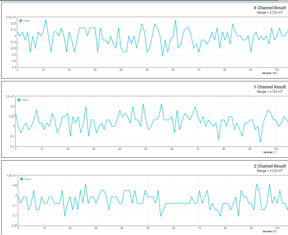
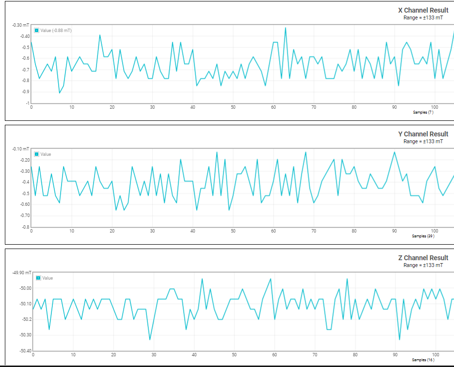
Figure 4-1 shows the X, Y, and Z magnetic flux densities measured by the TMAG5273 when the screw is fully unfastened like it is in Figure 1-1. Figure 4-2 shows a similar plot when the screw is fully fastened like it is in Figure 1-2. As shown in the plots, the Z-axis is the most affected by the linear displacement of the magnet. If the magnet was perfectly aligned so that it is centered with respect to the Hall elements within the device, the X and Y readings would go down to zero. Due to tolerances in the attachment and location of the Hall element within the device, however, the magnet is not centered with respect to the Hall element in this case, thereby resulting in small readings on the X and Y axes.
 Figure 4-1 Magnetic Flux Density Results
When Screw is Fully Unfastened From Base
Figure 4-1 Magnetic Flux Density Results
When Screw is Fully Unfastened From BaseFor these results, the magnet was placed so that the south pole of the magnet is near the top of the device package. The TMAG5273 readings are negative because the TMAG5273 defines a negative field as when the south pole of the magnet is applied near the top of its package. For devices like the TMAG5170 that define a positive field as when the south pole of the magnet is applied near its top, the sign of the results shown in Figure 4-1 and Figure 4-2 would be positive instead of negative.
 Figure 4-2 Magnetic Flux Density Results when Screw is Fully Fastened into Base