ZHCSX03F December 2002 – June 2024 ULQ2003A-Q1 , ULQ2004A-Q1
PRODUCTION DATA
- 1
- 1 特性
- 2 应用
- 3 说明
- 4 Pin Configuration and Functions
-
5 Specifications
- 5.1 Absolute Maximum Ratings
- 5.2 ESD Ratings
- 5.3 Recommended Operating Conditions
- 5.4 Thermal Information
- 5.5 Electrical Characteristics, ULQ2003AT and ULQ2003AQ
- 5.6 Electrical Characteristics, ULQ2004AT
- 5.7 Switching Characteristics, ULQ2003A and ULQ2004A
- 5.8 Dissipation Ratings
- 5.9 Typical Characteristics
- 6 Parameter Measurement Information
- 7 Detailed Description
- 8 Application and Implementation
- 9 Device and Documentation Support
- 10Revision History
- 11Mechanical, Packaging, and Orderable Information
封装选项
请参考 PDF 数据表获取器件具体的封装图。
机械数据 (封装 | 引脚)
- PW|16
- DYY|16
- D|16
散热焊盘机械数据 (封装 | 引脚)
订购信息
8.2.2.3 Power Dissipation and Temperature
The number of coils driven is dependent on the coil current and on-chip power dissipation. The number of coils driven can be determined by Figure 8-2.
For a more accurate determination of number of coils possible, use Equation 2 to calculate ULQ200xA-Q1 device on-chip power dissipation PD:
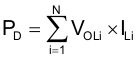
where
- N is the number of channels active together
- VOLi is the OUTi pin voltage for the load current ILi. This is the same as VCE(SAT)
To ensure reliability of ULQ200xA-Q1 device and the system, the on-chip power dissipation must be lower that or equal to the maximum allowable power dissipation (PD(MAX)) dictated by Equation 3.
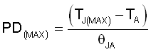
where
- TJ(max) is the target maximum junction temperature
- TA is the operating ambient temperature
- RθJA is the package junction to ambient thermal resistance
Limit the die junction temperature of the ULQ200xA-Q1 device to less than 125°C. The IC junction temperature is directly proportional to the on-chip power dissipation.