ZHCSIF5F December   2015  – April 2019 TPS99000-Q1

PRODUCTION DATA.  

  1. 特性
  2. 应用
  3. 说明
    1.     典型的独立系统
  4. 修订历史记录
  5. Pin Configuration and Functions
    1.     Pin Functions - Initialization, Clock, and Diagnostics
    2.     Pin Functions - Power and Ground
    3.     Pin Functions - Power Supply Management
    4.     Pin Functions - Illumination Control
    5.     Pin Functions - Serial Peripheral Interfaces
    6.     Pin Functions - Analog to Digital Converter
  6. Specifications
    1. 6.1  Absolute Maximum Ratings
    2. 6.2  ESD Ratings
    3. 6.3  Recommended Operating Conditions
    4. 6.4  Thermal Information
    5. 6.5  Electrical Characteristics - Transimpedance Amplifier Parameters
    6. 6.6  Electrical Characteristics - Digital to Analog Converters
    7. 6.7  Electrical Characteristics - Analog to Digital Converter
    8. 6.8  Electrical Characteristics - FET Gate Drivers
    9. 6.9  Electrical Characteristics - Photo Comparator
    10. 6.10 Electrical Characteristics - Voltage Regulators
    11. 6.11 Electrical Characteristics - Temperature and Voltage Monitors
    12. 6.12 Electrical Characteristics - Current Consumption
    13. 6.13 Power-Up Timing Requirements
    14. 6.14 Power-Down Timing Requirements
    15. 6.15 Timing Requirements - Sequencer Clock
    16. 6.16 Timing Requirements - Host / Diagnostic Port SPI Interface
    17. 6.17 Timing Requirements - ADC Interface
    18. 6.18 Switching Characteristics
  7. Detailed Description
    1. 7.1 Overview
    2. 7.2 Functional Block Diagram
    3. 7.3 Feature Description
      1. 7.3.1 Illumination Control
        1. 7.3.1.1 Illumination System High Dynamic Range Dimming Overview
        2. 7.3.1.2 Illumination Control Loop
        3. 7.3.1.3 Continuous Mode Operation
          1. 7.3.1.3.1 Output Capacitance in Continuous Mode
          2. 7.3.1.3.2 Continuous Mode Driver Distortion and Blanking Current
          3. 7.3.1.3.3 Continuous Mode S_EN2 Dissipative Load Shunt Options
          4. 7.3.1.3.4 Continuous Mode Constant OFF Time
          5. 7.3.1.3.5 Continuous Mode Current Limit
        4. 7.3.1.4 Discontinuous Mode Operation
          1. 7.3.1.4.1 Discontinuous Mode Pulse Width Limit
          2. 7.3.1.4.2 COMPOUT_LOW Timer in Discontinuous Operation
          3. 7.3.1.4.3 Dimming Within Discontinuous Operation Range
          4. 7.3.1.4.4 Multiple Pulse Heights to Increase Bit Depth
          5. 7.3.1.4.5 TIA Gain Adjustment
          6. 7.3.1.4.6 Current Limit in Discontinuous Mode
          7. 7.3.1.4.7 CMODE Big Cap Mode in Discontinuous Operation
      2. 7.3.2 Over-Brightness Detection
        1. 7.3.2.1 Photo Feedback Monitor BIST
        2. 7.3.2.2 Excessive Brightness BIST
      3. 7.3.3 Analog to Digital Converter
        1. 7.3.3.1 Analog to Digital Converter Input Table
      4. 7.3.4 Power Sequencing and Monitoring
        1. 7.3.4.1 Power Monitoring
      5. 7.3.5 DMD Mirror Voltage Regulator
      6. 7.3.6 Low Dropout Regulators
      7. 7.3.7 System Monitoring Features
        1. 7.3.7.1 Windowed Watchdog Circuits
        2. 7.3.7.2 Die Temperature Monitors
        3. 7.3.7.3 External Clock Ratio Monitor
      8. 7.3.8 Communication Ports
        1. 7.3.8.1 Serial Peripheral Interface (SPI)
    4. 7.4 Device Functional Modes
      1. 7.4.1 OFF
      2. 7.4.2 STANDBY
      3. 7.4.3 POWERING_DMD
      4. 7.4.4 DISPLAY_RDY
      5. 7.4.5 DISPLAY_ON
      6. 7.4.6 PARKING
      7. 7.4.7 SHUTDOWN
    5. 7.5 Register Maps
      1. 7.5.1 System Status Registers
      2. 7.5.2 ADC Control
      3. 7.5.3 General Fault Status
  8. Application and Implementation
    1. 8.1 Application Information
    2. 8.2 Typical Applications
      1. 8.2.1 HUD
        1. 8.2.1.1 Design Requirements
        2. 8.2.1.2 Application Design Considerations
          1. 8.2.1.2.1 Photodiode Considerations
          2. 8.2.1.2.2 LED Current Measurement
          3. 8.2.1.2.3 Setting the Current Limit
          4. 8.2.1.2.4 Input Voltage Variation Impact
          5. 8.2.1.2.5 Discontinuous Mode Photo Feedback Considerations
          6. 8.2.1.2.6 Transimpedance Amplifiers (TIAs, Usage, Offset, Dark Current, Ranges, RGB Trim)
      2. 8.2.2 Headlight
        1. 8.2.2.1 Design Requirements
  9. Power Supply Recommendations
    1. 9.1 TPS99000-Q1 Power Supply Architecture
    2. 9.2 TPS99000-Q1 Power Outputs
    3. 9.3 Power Supply Architecture
  10. 10Layout
    1. 10.1 Layout Guidelines
      1. 10.1.1 Power/High Current Signals
      2. 10.1.2 Sensitive Analog Signals
      3. 10.1.3 High Speed Digital Signals
      4. 10.1.4 High Power Current Loops
      5. 10.1.5 Kelvin Sensing Connections
      6. 10.1.6 Ground Separation
  11. 11器件和文档支持
    1. 11.1 器件支持
      1. 11.1.1 第三方产品免责声明
    2. 11.2 商标
    3. 11.3 静电放电警告
    4. 11.4 术语表
  12. 12机械、封装和可订购信息
    1. 12.1 Package Option Addendum
      1. 12.1.1 Tape and Reel Information
      2. 12.1.2 Mechanical Drawings

封装选项

机械数据 (封装 | 引脚)
散热焊盘机械数据 (封装 | 引脚)
订购信息

说明

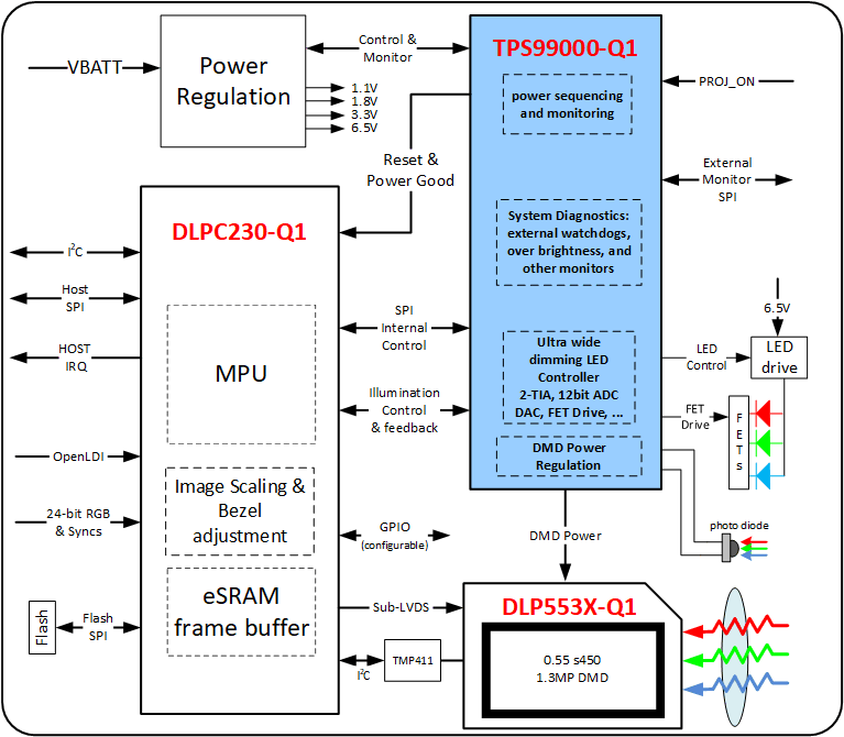
TPS99000-Q1 系统管理和照明控制器是 DLP553x-Q1 芯片组的组成部分,其中还包含 DLPC230-Q1 DMD 显示控制器。 该芯片组的亮度要求范围典型值为 3 至 15,000 尼特,具有严格的颜色点控制,能够为平视显示屏 (HUD) 应用提供支持所需的所有功能和超越典型 5000:1 显示器的调光要求。

集成式 DMD 高压稳压器电源可提供 DMD 镜像基准电压,满足严格容差的要求。电源序列发生器和监控器为整个芯片组的加电和断电事件提供可靠协同。

TPS99000-Q1照明控制器集成了一个 12 位 ADC、两个 DAC(12 位和 10 位)以及两个高性能光电二极管信号调节和跨阻放大器 (TIA)照明控制系统的核心组件之一。该 ADC 能够自动对每个视频帧进行高达 63 次事件采样。

先进的系统状态监控电路可提供实时图像,以显示子系统的运行情况,包括两个处理器看门狗电路、两个裸片温度监控器、用于过压和欠压检测的综合电源监控、在 SPI 总线事务上通过字节级奇偶校验获得的校验和以及密码寄存器保护、高亮监视器电路以及其他内置测试功能。

器件信息(1)

器件型号 封装 封装尺寸(标称值)
TPS99000-Q1 HTQFP (100) 14.00mm × 14.00mm
  1. 如需了解所有可用封装,请参阅数据表末尾的可订购产品附录。

典型的独立系统

TPS99000-Q1 toplevel_blockdiagram_tps99000_v6.gif