ZHCSHZ2E December   2014  – March 2022 TPS62406-Q1 , TPS62407-Q1 , TPS62422-Q1 , TPS62423-Q1 , TPS62424-Q1

PRODUCTION DATA  

  1. 特性
  2. 应用
  3. 说明
  4. Revision History
  5. Device Comparison Table
  6. Pin Configuration and Functions
  7. Specifications
    1. 7.1 Absolute Maximum Ratings
    2. 7.2 ESD Ratings
    3. 7.3 Recommended Operating Conditions
    4. 7.4 Thermal Information
    5. 7.5 Electrical Characteristics
    6. 7.6 Timing Requirements
    7. 7.7 Switching Characteristics
    8. 7.8 Typical Characteristics
  8. Detailed Description
    1. 8.1 Overview
      1. 8.1.1 Converter 1
      2. 8.1.2 Converter 2
    2. 8.2 Functional Block Diagram
    3. 8.3 Feature Description
      1. 8.3.1 Enable
      2. 8.3.2 DEF_1 Pin Function
      3. 8.3.3 180° Out-of-Phase Operation
      4. 8.3.4 Short-Circuit Protection
      5. 8.3.5 Thermal Shutdown
      6. 8.3.6 EasyScale Interface: One-Pin Serial Interface for Dynamic Output-Voltage Adjustment
        1. 8.3.6.1 General
        2. 8.3.6.2 Protocol
    4. 8.4 Device Functional Modes
      1. 8.4.1 Power-Save Mode
        1. 8.4.1.1 Dynamic Voltage Positioning
        2. 8.4.1.2 Soft Start
        3. 8.4.1.3 100% Duty-Cycle Low-Dropout Operation
        4. 8.4.1.4 Undervoltage Lockout
      2. 8.4.2 Mode Selection
    5. 8.5 Programming
      1. 8.5.1 Addressable Registers
        1. 8.5.1.1 Bit Decoding
        2. 8.5.1.2 Acknowledge
        3. 8.5.1.3 Mode Selection
  9. Application and Implementation
    1. 9.1 Application Information
      1. 9.1.1 Application Information
    2. 9.2 Typical Application
      1. 9.2.1 Design Requirements
      2. 9.2.2 Detailed Design Procedure
        1. 9.2.2.1 Output Voltage Setting
          1. 9.2.2.1.1 Converter 1 Fixed Default Output-Voltage Setting
          2. 9.2.2.1.2 Converter 2 Fixed Default Output-Voltage Setting
        2. 9.2.2.2 Output Filter Design (Inductor and Output Capacitor)
          1. 9.2.2.2.1 Inductor Selection
          2. 9.2.2.2.2 Output-Capacitor Selection
          3. 9.2.2.2.3 Input Capacitor Selection
      3. 9.2.3 Application Curves
    3. 9.3 System Examples
  10. 10Power Supply Recommendations
  11. 11Layout
    1. 11.1 Layout Guidelines
    2. 11.2 Layout Example
  12. 12Device and Documentation Support
    1. 12.1 支持资源
    2. 12.2 接收文档更新通知
    3. 12.3 Trademarks
    4. 12.4 Electrostatic Discharge Caution
    5. 12.5 术语表
  13. 13Mechanical, Packaging, and Orderable Information

封装选项

机械数据 (封装 | 引脚)
散热焊盘机械数据 (封装 | 引脚)
订购信息

说明

TPS624xx-Q1 器件系列是适用于汽车应用(例如高级驾驶辅助系统 (ADAS))的双路同步降压直流/直流转换器。该系列可提供两组由标准 3.3 V 或 5 V 电压轨供电的独立输出电压轨,以及经过优化的固定输出电压,为 ADAS 摄像头模块中的 CMOS 成像仪或串行器-解串器供电。

EasyScale™ 串行接口支持在运行过程中对输出电压进行修改。固定输出电压版本 TPS624xx-Q1 支持对低功耗处理器进行单引脚控制的简单动态电压调节。

TPS624xx-Q1 器件系列可在 2.25 MHz 固定开关频率下运行,在轻负载电流情况下会进入省电模式,以便在整个负载电流范围内保持高效率。对于低噪声应用,可通过拉高 MODE/DATA 引脚来强制器件进入固定频率 PWM 模式。关断模式可以将电流消耗降低至 1.2 μA 的典型值。此器件允许使用小型电感器和电容器,可实现一个小型解决方案尺寸。

器件信息(1)
器件型号封装封装尺寸(标称值)
TPS62406-Q1VSON (10)3.00mm × 3.00mm
TPS62407-Q1
TPS62422-Q1
TPS62423-Q1
TPS62424-Q1
如需了解所有可用封装,请参阅数据表末尾的可订购产品附录。
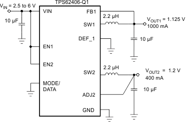
GUID-578B43C7-597E-4287-8358-021A5FE67C1F-low.gif简化版原理图
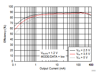
GUID-CA5194FC-135F-470A-AF05-9C6B823A9463-low.gifTPS62406-Q1 效率与输出电流间的关系, VOUT2