ZHCS165B April 2011 – October 2014 TPS55010
PRODUCTION DATA.
- 1 特性
- 2 应用
- 3 说明
- 4 简化电路原理图
- 5 修订历史记录
- 6 Pin Configuration and Functions
- 7 Specifications
-
8 Detailed Description
- 8.1 Overview
- 8.2 Functional Block Diagram
- 8.3
Feature Description
- 8.3.1 Fixed Frequency PWM Control
- 8.3.2 Half Bridge and Bootstrap Voltage
- 8.3.3 Error Amplifier
- 8.3.4 Voltage Reference
- 8.3.5 Adjusting the Output Voltage
- 8.3.6 Enable and Adjusting Undervoltage Lockout
- 8.3.7 Adjusting Slow Start Time
- 8.3.8 Constant Switching Frequency and Timing Resistor (RT/CLK Pin)
- 8.3.9 How to Interface to RT/CLK Pin
- 8.3.10 Overcurrent Protection
- 8.3.11 Reverse Overcurrent Protection
- 8.3.12 FAULT Pin
- 8.3.13 Thermal Shutdown
- 8.4 Device Functional Modes
-
9 Application And Implementation
- 9.1 Application Information
- 9.2
Typical Applications
- 9.2.1 Design Guide - Step-by-Step Design Procedure
- 9.2.2 Primary Side Voltage
- 9.2.3 Voltage Feedback
- 9.2.4 Selecting the Switching Frequency and Primary Inductance
- 9.2.5 Primary Side Capacitor
- 9.2.6 Secondary Side Diode
- 9.2.7 Secondary Side Capacitor
- 9.2.8 Input Capacitor
- 9.2.9 Y - Capacitor
- 9.2.10 Slow Start Capacitor
- 9.2.11 Bootstrap Capacitor Selection
- 9.2.12 UVLO Resistors
- 9.2.13 Compensation
- 9.2.14 Design Tips
- 9.2.15 How to Specify a Fly-Buck Transformer
- 9.2.16 Application Curves
- 9.3 Typical Application, Dual Output
- 10Power Supply Recommendations
- 11Layout
- 12器件和文档支持
- 13机械封装和可订购信息
1 特性
2 应用
- PLC 抗噪、数据采集和测量设备
- 隔离式 RS-232 和 RS-485 通信通道
- 为线路驱动器、ISO 放大器、传感器、CAN 收发器供电
- 为 IGBT 栅极驱动器提供浮动式电源
- 提升医疗设备安全性
3 说明
TPS55010 是一款用于为隔离式接口(例如,RS-485 和 RS-232)提供 3.3V 或 5V 隔离输入电源的变压器驱动器。
该器件使用固定频率电流模式控制和具有一次侧反馈的半桥功率级,可稳定高达 2W 功耗级别的输出电压。开关频率可在 100kHz 至 2000kHz 范围内调节,因此可以优化解决方案的尺寸、效率和抗噪性能。开关频率由电阻器设置,或通过 RT/CLK 引脚与外部时钟同步。为了最大限度减少浪涌电流,可以向 SS 引脚上连接一个小电容器。可以使用 EN 引脚作为启用引脚或用于在 2.6V 的基础上提高默认的输入 UVLO 电压。
通过使用同款变压器,TPS55010 可调整一次侧电压,为不同的输入和输出电压组合提供解决方案。现有的变压器可提供单路正输出电压、双路正输出电压和双路负输出电压。
TPS55010 采用 3mm x 3mm 16 引脚、带散热焊盘的 QFN 封装。
器件信息 (1)
| 部件号 | 封装 | 封装尺寸(标称值) |
|---|---|---|
| TPS55010 | WQFN (16) | 3.00mm x 3.00mm |
- 要了解所有可用封装,请参见数据表末尾的可订购产品附录。
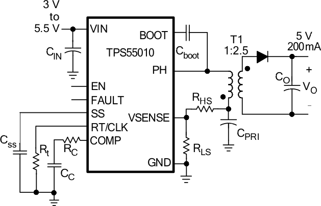
4 简化电路原理图

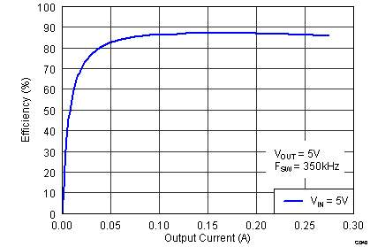
效率与负载电流间的关系
