ZHCSE79C March   2011  – September 2015

PRODUCTION DATA.  

  1. 特性
  2. 应用
  3. 说明
  4. 修订历史记录
  5. Pin Configuration and Functions
  6. Specifications
    1. 6.1 Absolute Maximum Ratings
    2. 6.2 ESD Ratings
    3. 6.3 Recommended Operating Conditions
    4. 6.4 Thermal Information
    5. 6.5 Electrical Characteristics
    6. 6.6 Operating Characteristics
    7. 6.7 Timing Requirements
    8. 6.8 Typical Characteristics
  7. Detailed Description
    1. 7.1 Overview
    2. 7.2 Functional Block Diagram
    3. 7.3 Feature Description
    4. 7.4 Device Functional Modes
      1. 7.4.1 Shutdown Mode
      2. 7.4.2 Voltage Divider Mode
      3. 7.4.3 Rheostat Mode
    5. 7.5 Programming with I2C
      1. 7.5.1 I2C General Operation
        1. 7.5.1.1 I2C Interface
        2. 7.5.1.2 START and STOP Conditions
        3. 7.5.1.3 Data Validity and Byte Formation
        4. 7.5.1.4 Acknowledge (ACK) and Not Acknowledge (NACK)
      2. 7.5.2 I2C Write and Read Operation
        1. 7.5.2.1 Auto Increment Function
        2. 7.5.2.2 Write Operation
        3. 7.5.2.3 Repeated Start
        4. 7.5.2.4 Read Operation
    6. 7.6 Register Maps
      1. 7.6.1 Slave Address
      2. 7.6.2 TPL0102 Register Map
      3. 7.6.3 IVRA (Initial Value Register for Potentiometer A)
      4. 7.6.4 WRA (Wiper Resistance Register for Potentiometer A)
      5. 7.6.5 IVRB (Initial Value Register for Potentiometer B)
      6. 7.6.6 WRB (Wiper Resistance Register for Potentiometer B)
      7. 7.6.7 ACR (Access Control Register)
  8. Application and Implementation
    1. 8.1 Application Information
    2. 8.2 Typical Applications
      1. 8.2.1 Adjustable Gain Non-Inverting Amplifier
        1. 8.2.1.1 Design Requirements
        2. 8.2.1.2 Detailed Design Procedure
        3. 8.2.1.3 Application Curves
      2. 8.2.2 Digital to Analog Converter (DAC)
        1. 8.2.2.1 Design Requirements
        2. 8.2.2.2 Detailed Design Procedure
        3. 8.2.2.3 Application Curves
      3. 8.2.3 Variable Current Sink
        1. 8.2.3.1 Design Requirements
        2. 8.2.3.2 Detailed Design Procedure
          1. 8.2.3.2.1 Compensation Components
        3. 8.2.3.3 Application Curves
  9. Power Supply Recommendations
    1. 9.1 Power Sequence
    2. 9.2 Wiper Position Upon Power Up
    3. 9.3 Dual-Supply vs Single-Supply
  10. 10Layout
    1. 10.1 Layout Guidelines
    2. 10.2 Layout Example
  11. 11器件和文档支持
    1. 11.1 社区资源
    2. 11.2 商标
    3. 11.3 静电放电警告
    4. 11.4 Glossary
  12. 12机械、封装和可订购信息

封装选项

机械数据 (封装 | 引脚)
散热焊盘机械数据 (封装 | 引脚)
订购信息

1 特性

  • 两个分辨率为 256 个位置的电位计
  • 非易失性存储器存储抽头设置
  • 100kΩ 端到端电阻 (TPL0102-100)
  • 短暂的抽头设置上电响应时间:< 100µs
  • ±0.5 最低有效位 (LSB) 积分非线性 (INL),±0.25 LSB 微分非线性 (DNL)(分压模式)
  • 4ppm/°C 比例温度系数
  • 兼容 I2C 的串行接口
  • 2.7V 至 5.5V 单电源运行
  • ±2.25V 至 ±2.75V 双电源运行
  • 工作温度范围:-40°C 至 85°C
  • 关断模式
  • 静电放电 (ESD) 性能测试符合 JESD 22 标准
    • 2000V 人体模型(A114-B,II 类)
    • 1000V 充电器件模型 (C101)

2 应用

  • 可调节增益放大器和偏移修整
  • 可调节电源
  • 设定点阈值的精度校准
  • 传感器微调和校准
  • 机械电位器的替代产品

3 说明

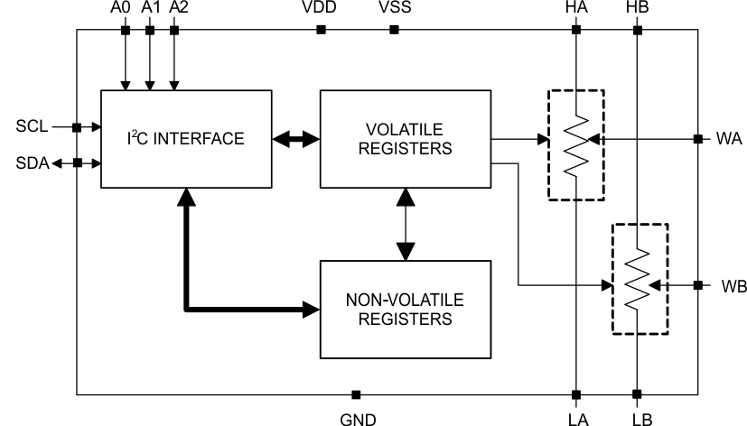
TPL0102 配有两个具备 256 个抽头位置的线性抽头数字电位计 (DPOT)。每个分压器可用作三端分压器或者两端变阻器。TPL0102-100 具有一个 100kΩ 端到端电阻。

TPL0102 配有非易失性存储器 (EEPROM),可用于存储抽头位置。这一点的优势是即使在掉电期间也可存储抽头位置。因此,再次上电时便可自动恢复抽头位置。TPL0102 的内部寄存器可以使用 I2C 接口进行访问。

TPL0102 采用 14 引脚 MicroQFN 和 14 引脚薄型小外形尺寸 (TSSOP) 封装,额定温度范围为 -40°C 至 85°C。

器件信息(1)

器件型号 封装 封装尺寸(标称值)
TPL0102 X2QFN (14) 2.00mm x 2.00mm
TSSOP (14) 5.00mm x 4.40mm
  1. 要了解所有可用封装,请见数据表末尾的可订购产品附录。

简化电路原理图

TPL0102 fbd_LIS134.gif