ZHCSCM7E July   2018  – February 2022 REF2025 , REF2030 , REF2033 , REF2041

PRODUCTION DATA  

  1. 特性
  2. 应用
  3. 说明
  4. Revision History
  5. Device Comparison Table
  6. Pin Configuration and Functions
    1.     Pin Functions
  7. Specifications
    1. 7.1 Absolute Maximum Ratings
    2. 7.2 ESD Ratings
    3. 7.3 Recommended Operating Conditions
    4. 7.4 Thermal Information
    5. 7.5 Electrical Characteristics
    6. 7.6 Typical Characteristics
  8. Parameter Measurement Information
    1. 8.1 Solder Heat Shift
    2. 8.2 Long-Term Stability
    3. 8.3 Thermal Hysteresis
    4. 8.4 Noise Performance
  9. Detailed Description
    1. 9.1 Overview
    2. 9.2 Functional Block Diagram
    3. 9.3 Feature Description
      1. 9.3.1 VREF and VBIAS Tracking
      2. 9.3.2 Low Temperature Drift
      3. 9.3.3 Load Current
    4. 9.4 Device Functional Modes
  10. 10Applications and Implementation
    1. 10.1 Application Information
    2. 10.2 Typical Application
      1. 10.2.1 Low-Side, Current-Sensing Application
        1. 10.2.1.1 Design Requirements
        2. 10.2.1.2 Detailed Design Procedure
          1. 10.2.1.2.1 Shunt Resistor
          2. 10.2.1.2.2 Differential Amplifier
          3. 10.2.1.2.3 Voltage Reference
          4. 10.2.1.2.4 Results
        3. 10.2.1.3 Application Curves
  11. 11Power-Supply Recommendations
  12. 12Layout
    1. 12.1 Layout Guidelines
    2. 12.2 Layout Example
  13. 13Device and Documentation Support
    1. 13.1 Documentation Support
      1. 13.1.1 Related Documentation
    2. 13.2 接收文档更新通知
    3. 13.3 支持资源
    4. 13.4 Trademarks
    5. 13.5 Electrostatic Discharge Caution
    6. 13.6 术语表
  14. 14Mechanical, Packaging, and Orderable Information

封装选项

机械数据 (封装 | 引脚)
散热焊盘机械数据 (封装 | 引脚)
订购信息

VREF and VBIAS Tracking

Most single-supply systems require an additional stable voltage in the middle of the analog-to-digital converter (ADC) input range to bias input bipolar signals. The VREF and VBIAS outputs of the REF20xx are generated from the same band-gap voltage as shown in the Section 9.2 section. Hence, both outputs track each other over the full temperature range of –40°C to 125°C with an accuracy of 7 ppm/°C (maximum). The tracking accuracy increases to 6 ppm/°C (maximum) when the temperature range is limited to –40°C to 85°C. The tracking error is calculated using the box method, as described by Equation 2:

Equation 2. GUID-A5E3EA1D-4964-4D9A-9221-E74407AF6BCB-low.gif

where

  • GUID-1D4819EB-BE0A-449E-8630-7EEB6812475A-low.gif

The tracking accuracy is as shown in Figure 9-1.
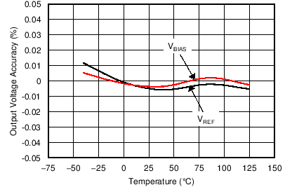
GUID-2F48F8E4-2F91-4784-A0F6-9684489F2ED6-low.pngFigure 9-1 VREF and VBIAS Tracking vs Temperature