ZHCS075A June 2012 – September 2015 PCM2903C
PRODUCTION DATA.
- 1 特性
- 2 应用
- 3 说明
- 4 修订历史记录
- 5 Device Comparison Table
- 6 Pin Configuration and Functions
-
7 Specifications
- 7.1 Absolute Maximum Ratings
- 7.2 ESD Ratings
- 7.3 Recommended Operating Conditions
- 7.4 Thermal Information
- 7.5 Electrical Characteristics
- 7.6
Typical Characteristics
- 7.6.1 Typical Characteristics: ADC
- 7.6.2 Typical Characteristics: DAC
- 7.6.3 Typical Characteristics: ADC Output Spectrum
- 7.6.4 Typical Characteristics: DAC Output Spectrum
- 7.6.5 Typical Characteristics: Supply Current
- 7.6.6 Typical Characteristics: ADC Digital Decimation Filter Frequency Response
- 7.6.7 Typical Characteristics: ADC Digital High-Pass Filter Frequency Response
- 7.6.8 Typical Characteristics: ADC Analog Antialiasing Filter Frequency Response
- 7.6.9 Typical Characteristics: DAC Digital Interpolation Filter Frequency Response
- 7.6.10 Typical Characteristics: DAC Analog Fir Filter Frequency Response
- 7.6.11 Typical Characteristics: DAC Analog Low-Pass Filter Frequency Response
- 8 Parameter Measurement Information
- 9 Detailed Description
- 10Application and Implementation
- 11Power Supply Recommendations
- 12Layout
- 13器件和文档支持
- 14机械、封装和可订购信息
9 Detailed Description
9.1 Overview
The PCM2903C is an audio codec with USB connection capability and a digital S/PDIF digital interface. The PCM2903C is a self-powered device; it needs an external 3.3V voltage source. The PCM2903C meet the requirements of USB1.1 standard connection. This device has analog and digital inputs and outputs; it has a digital S/PDIF interface for input and output data. The PCM2903C has 3 external interrupts (HID) which control the Mute, Volume Up and Volume Down, these control inputs are active High. The PCM2903C requires a 12MHz clock; it can be provided by an external clock or generated by a built-in crystal resonator.
9.2 Functional Block Diagram
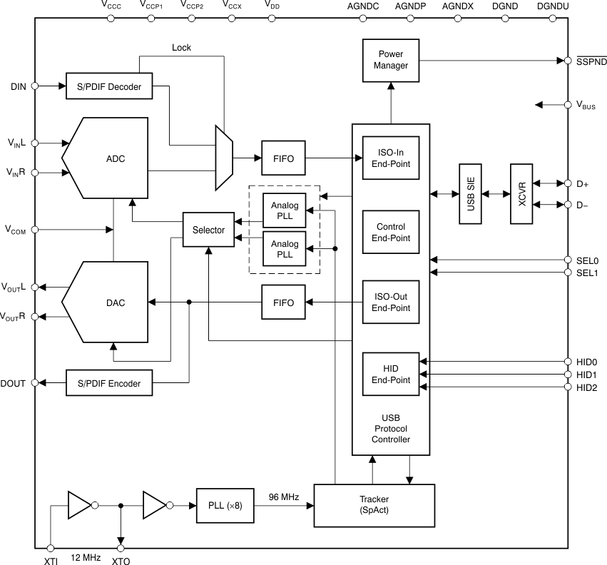
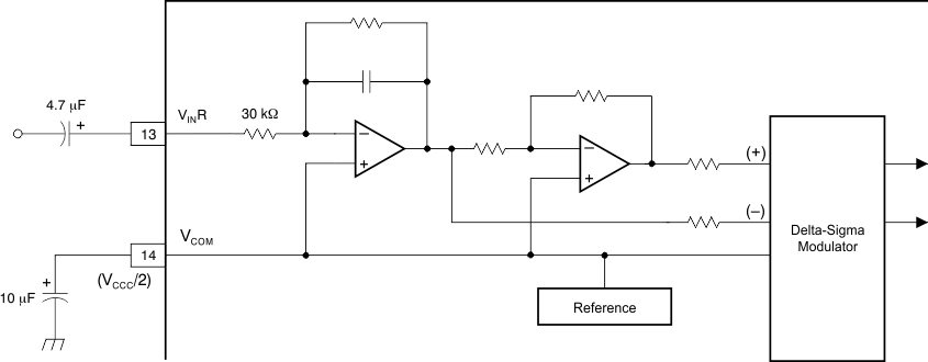 Figure 34. Block Diagram of Analog Front-End (Right Channel)
9.3 Feature Description
9.3.1 End-Points
The PCM2903C has the following four end-points:
- Control end-point (EP number 0)
- Isochronous-out audio data stream end-point (EP number 2)
- Isochronous-in audio data stream end-point (EP number 4)
- HID end-point (EP number 5)
The control end-point is a default end-point. The control end-point is used to control all functions of the PCM2903C by the standard USB request and an USB audio class specific request from the host. The isochronous-out audio data stream end-point is an audio sink end-point, which receives the PCM audio data. The isochronous-out audio data stream end-point accepts the adaptive transfer mode. The isochronous-in audio data stream end-point is an audio source end-point that transmits the PCM audio data. The isochronous-in audio data stream end-point uses asynchronous transfer mode. The HID end-point is an interrupt-in end-point. HID end-point reports HID0, HID1, and HID2 pin status every 32 ms.
The human interface device (HID) pins are defined as consumer control devices. The HID function is designed as an independent end-point from both isochronous-in and -out end-points. Therefore, the result obtained from the HID operation depends on the host software. Typically, the HID function is used as the primary audio-out device.
9.3.2 Clock and Reset
The PCM2903C requires a 12-MHz (±500 ppm) clock for the USB and audio function, which can be generated by a built-in crystal oscillator with a 12-MHz crystal resonator or supplied by an external clock. The 12-MHz crystal resonator must be connected to XTI (pin 21) and XTO (pin 20) with one high (1-MΩ) resistor and two small capacitors, the capacitance of which depends on the load capacitance of the crystal resonator. If the external clock is used, the clock must be supplied to XTI, and XTO must be open.
The PCM2903C has an internal power-on reset circuit, which triggers automatically when VDD (pin 27) exceeds 2.5 V typical (2.7 V to 2.2 V). Approximately 700 μs is required until internal reset release.
9.3.3 Digital Audio Interface
The PCM2903C employs both S/PDIF input and output. Isochronous-out data from the host are encoded to the S/PDIF output and the DAC analog output. Input data are selected as either S/PDIF or ADC analog input. When the device detects an S/PDIF input and successfully locks on the received data, the isochronous-in transfer data source is automatically selected from S/PDIF itself; otherwise, the data source selected is the ADC analog input.
This feature is a customer option. It is the responsibility of the user to implement this feature.
9.3.4 Supported Input/Output Data
The following data formats are accepted by the S/PDIF input and output. All other data formats are unable to use S/PDIF.
- 48-kHz 16-bit stereo
- 44.1-kHz 16-bit stereo
- 32-kHz 16-bit stereo
Any mismatch of the sampling rate between the input S/PDIF signal and the host command is not acceptable. Any mismatch of the data format between the input S/PDIF signal and the host command may cause unexpected results, with the following exceptions:
- Recording in monaural format from stereo data input at the same data rate
- Recording in 8-bit format from 16-bit data input at the same data rate
A combination of these two conditions is not acceptable.
For playback, all possible data-rate sources are converted to 16-bit stereo format at the same source data rate.
9.3.5 Channel Status Information
The channel status information is fixed as consumer application, PCM mode, copyright, and digital/digital converter. All other bits are fixed as 0's except for the sample frequency, which is set automatically according to the data received through the USB.
9.3.6 Copyright Management
Isochronous-in data are affected by the serial copy management system (SCMS). When the control bit indicates that the received digital audio data are original, the input digital audio data are transferred to the host. If the data are indicated as first generation or higher, the transferred data are routed to the analog input.
Digital audio data output is always encoded as original with SCMS control.
9.4 Device Functional Modes
The PCM2903C is a USB controlled device. The PCM2903C is a codec, so it has analog input (that goes to an A/D converter) and analog output (that comes from a D/A converter), alongside of the digital path that goes to USB and S/PDIF. A wider explanation of these operational modes is in Programming.
9.5 Programming
9.5.1 USB Interface
Control data and audio data are transferred to the PCM2903C via D+ (pin 1) and D– (pin 2). All data to and from the PCM2903C are transferred at full speed. The device descriprtor contains the information described in Table 1.
Table 1. Device Descriptor
| USB revision | 2.0 compliant |
| Device class | 0x00 (device-defined interface level) |
| Device subclass | 0x00 (not specified) |
| Device protocol | 0x00 (not specified) |
| Max packet size for end-point 0 | 8 bytes |
| Vendor ID | 0x08BB |
| Product ID | 0x29C3 |
| Device release number | 1.0 (0x0100) |
| Number of configurations | 1 |
| Vendor strings | String number 1 (see Table 3) |
| Product strings | String number 2 (see Table 3) |
| Serial number | Not supported |
The configuration descriptor contains the information described in Table 2.
Table 2. Configuration Descriptor
| Interface | Four interfaces |
| Power attribute | 0xC0 (self-powered, no remote wakeup) |
| Maximum power | 0x0A (20 mA) |
The string descriptor contains the information described in Table 3.
Table 3. String Descriptor
| Number 0 | 0x0409 |
| Number 1 | BurrBrown from Texas Instruments |
| Number 2 | USB Audio CODEC(1) |
9.5.2 Device Configuration
Figure 35 illustrates the USB audio function topology. The PCM2903C has four interfaces. Each interface consists of alternative settings.
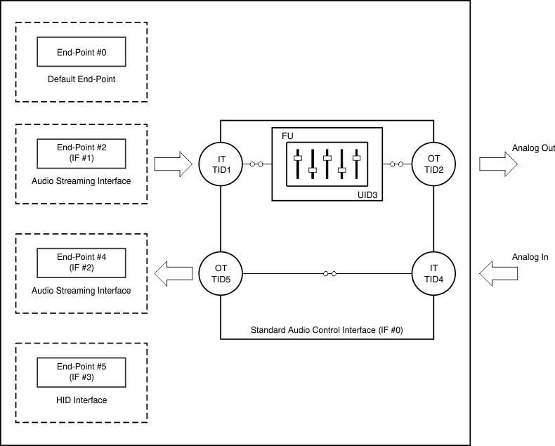 Figure 35. USB Audio Function Topology
9.5.2.1 Interface Number 0
Interface number 0 is the control interface. Alternative setting number 0 is the only possible setting for interface number 0. Alternative setting number 0 describes the standard audio control interface. The audio control interface consists of a single terminal. The PCM2903C has the following five terminals:
- Input terminal (IT number 1) for isochronous-out stream
- Output terminal (OT number 2) for audio analog output
- Feature unit (FU number 3) for DAC digital attenuator
- Input terminal (IT number 4) for audio analog input
- Output terminal (OT number 5) for isochronous-in stream
Input terminal number 1 is defined as USB stream (terminal type 0x0101). Input terminal number 1 can accept two-channel audio streams consisting of left and right channels. Output terminal number 2 is defined as a speaker (terminal type 0x0301). Input terminal number 4 is defined as a line connector (terminal type 0x0603). Output terminal number 5 is defined as a USB stream (terminal type 0x0101). Output terminal number 5 can generate two-channel audio streams composed of left and right channel data. Feature unit number 3 supports the following sound control features:
- Volume control
- Mute control
The built-in digital volume controller can be manipulated by an audio class specific request from 0 dB to –64 dB in 1-dB steps. Changes are made by incrementing or decrementing by one step (1 dB) for every 1/fS time interval until the volume level has reached the requested value. Each channel can be set for different values. The master volume control is not supported. A request to the master volume is stalled and ignored. The built-in digital mute controller can be manipulated by audio class-specific request. A master mute control request is acceptable. A request to an individual channel is stalled and ignored.
9.5.2.2 Interface Number 1
Interface number 1 is the audio streaming data-out interface. Interface number 1 has the five alternative settings described in Table 4. Alternative setting number 0 is the zero-bandwidth setting.
Table 4. Interface Number 1 Alternative Settings
| ALTERNATIVE SETTING |
DATA FORMAT |
TRANSFER MODE |
SAMPLING RATE (kHz) |
||
|---|---|---|---|---|---|
| 00 | Zero bandwidth | ||||
| 01 | 16-bit | Stereo | Twos complement (PCM) | Adaptive | 32, 44.1, 48 |
| 02 | 16-bit | Mono | Twos complement (PCM) | Adaptive | 32, 44.1, 48 |
| 03 | 8-bit | Stereo | Twos complement (PCM) | Adaptive | 32, 44.1, 48 |
| 04 | 8-bit | Mono | Twos complement (PCM) | Adaptive | 32, 44.1, 48 |
9.5.2.3 Interface Number 2
Interface number 2 is the audio streaming data-in interface. Interface number 2 has the 19 alternative settings described in Table 5. Alternative setting number 0 is the zero-bandwidth setting. All other alternative settings are operational settings.
Table 5. Interface Number 2 Alternative Settings
| ALTERNATIVE SETTING |
DATA FORMAT |
TRANSFER MODE |
SAMPLING RATE (kHz) |
||
|---|---|---|---|---|---|
| 00 | Zero bandwidth | ||||
| 01 | 16-bit | Stereo | Twos complement (PCM) | Asynchronous | 48 |
| 02 | 16-bit | Mono | Twos complement (PCM) | Asynchronous | 48 |
| 03 | 16-bit | Stereo | Twos complement (PCM) | Asynchronous | 44.1 |
| 04 | 16-bit | Mono | Twos complement (PCM) | Asynchronous | 44.1 |
| 05 | 16-bit | Stereo | Twos complement (PCM) | Asynchronous | 32 |
| 06 | 16-bit | Mono | Twos complement (PCM) | Asynchronous | 32 |
| 07 | 16-bit | Stereo | Twos complement (PCM) | Asynchronous | 22.05 |
| 08 | 16-bit | Mono | Twos complement (PCM) | Asynchronous | 22.05 |
| 09 | 16-bit | Stereo | Twos complement (PCM) | Asynchronous | 16 |
| 0A | 16-bit | Mono | Twos complement (PCM) | Asynchronous | 16 |
| 0B | 8-bit | Stereo | Twos complement (PCM) | Asynchronous | 16 |
| 0C | 8-bit | Mono | Twos complement (PCM) | Asynchronous | 16 |
| 0D | 8-bit | Stereo | Twos complement (PCM) | Asynchronous | 8 |
| 0E | 8-bit | Mono | Twos complement (PCM) | Asynchronous | 8 |
| 0F | 16-bit | Stereo | Twos complement (PCM) | Synchronous | 11.025 |
| 10 | 16-bit | Mono | Twos complement (PCM) | Synchronous | 11.025 |
| 11 | 8-bit | Stereo | Twos complement (PCM) | Synchronous | 11.025 |
| 12 | 8-bit | Mono | Twos complement (PCM) | Synchronous | 11.025 |
9.5.2.4 Interface Number 3
Interface number 3 is the interrupt data-in interface. Alternative setting number 0 is the only possible setting for interface number 3. Interface number 3 consists of the HID consumer control device and reports the status of these three key parameters:
- Mute (0xE209)
- Volume up (0xE909)
- Volume down (0xEA09)
9.5.3 Interface Sequence
9.5.3.1 Power On, Attach, and Playback Sequence
The PCM2903C is ready for setup when the reset sequence has finished and the USB bus is attached. In order to perform certain reset sequences defined in the USB specification, VDD, VCCC, VCCP1, VCCP2, and VCCX must rise up within 10 ms / 3.3 V. After connection has been established by setup, the PCM2903C is ready to accept USB audio data. While waiting, the audio data (idle state) and analog output are set to bipolar zero (BPZ).
When receiving the audio data, the PCM2903C stores the first audio packet, which contained 1-ms audio data, into the internal storage buffer. The PCM2903C starts playing the audio data when detecting the next start of frame (SOF) packet, as illustrated in Figure 36 and Figure 37.
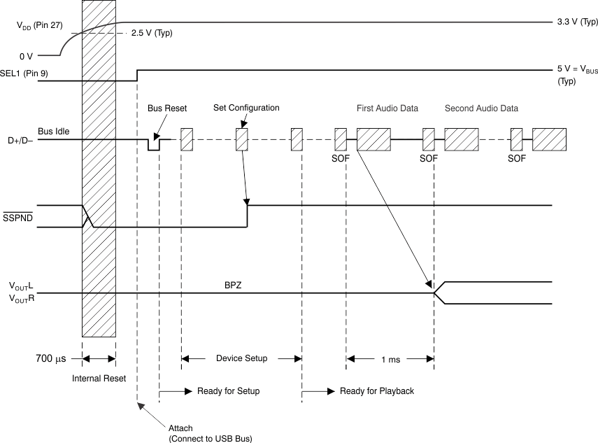 Figure 36. Attach After Poweron
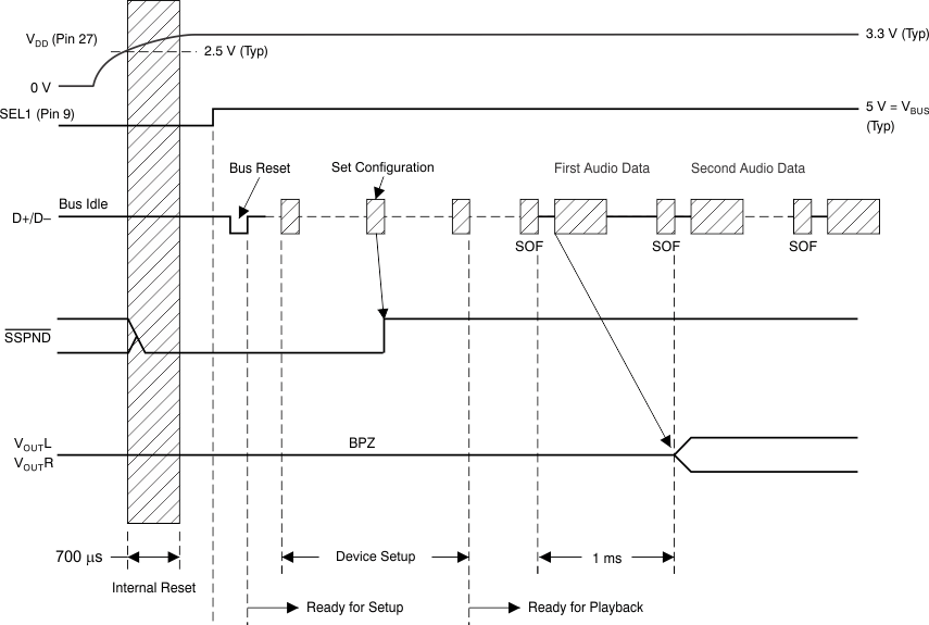 Figure 37. Poweron Under Attach
9.5.3.2 Play, Stop, and Detach Sequence
When the host finishes or aborts the playback, the PCM2903C stops playing after the last audio data have played, as shown in Figure 38.
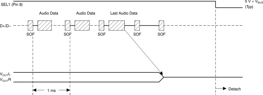 Figure 38. Play, Stop, and Detach Sequence
9.5.3.3 Record Sequence
The PCM2903C starts the audio capture into the internal memory after receiving the SET_INTERFACE command, as shown in Figure 39.
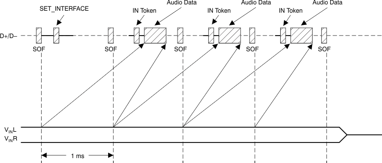 Figure 39. Record Sequence
9.5.3.4 Suspend and Resume Sequence
The PCM2903C enters the suspend state after it detects a constant idle state on the USB bus (approximately 5 ms), as shown in Figure 40. While the PCM2903C enters the suspend state, the SSPND flag (pin 28) is asserted. The PCM2903C wakes up immediately after detecting a non-idle state on the USB bus.
 Figure 40. Suspend and Resume Sequence