ZHCSOX1 October 2020 OPA455
PRODUCTION DATA
- 1 特性
- 2 应用
- 3 说明
- 4 Revision History
- 5 Pin Configuration and Functions
- 6 Specifications
- 7 Detailed Description
- 8 Application and Implementation
- 9 Power Supply Recommendations
- 10Layout
- 11Device and Documentation Support
- 12Mechanical, Packaging, and Orderable Information
10.1.6 Heat Dissipation
Power dissipated in the OPA455 causes the junction temperature to rise. For reliable operation, junction temperature must be limited to 125°C, maximum. Maintaining a lower junction temperature always results in higher reliability. Some applications require a heat sink to make sure that the maximum operating junction temperature is not exceeded. Junction temperature can be determined according to Equation 4:
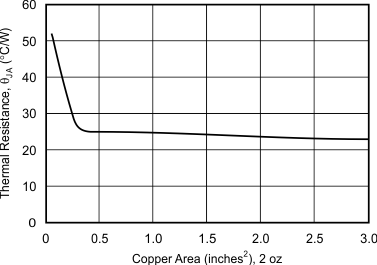
Package thermal resistance, RθJA , is affected by mounting techniques and environments. Poor air circulation and use of sockets can significantly increase thermal resistance to the ambient environment. Many op amps placed closely together also increase the surrounding temperature. Best thermal performance is achieved by soldering the op amp onto a circuit board with wide printed circuit traces to allow greater conduction through the op amp leads. Increasing circuit board copper area to approximately 0.5 in2 decreases thermal resistance; however, minimal improvement occurs beyond 0.5 in2, as shown in Figure 10-3.
For additional information on determining heat sink requirements, consult the Heat Sinking—TO-3 Thermal Model application bulletin, available for download at www.ti.com.
 Figure 10-3 Thermal Resistance vs Circuit Board Copper Area