ZHCSKG0J October   2019  – April 2021 OPA2607 , OPA607

PRODUCTION DATA  

  1. 特性
  2. 应用
  3. 说明
  4. Revision History
  5. Device Comparison
  6. Pin Configuration and Functions
  7. Specifications
    1. 7.1 Absolute Maximum Ratings
    2. 7.2 ESD Ratings
    3. 7.3 Recommended Operating Conditions
    4. 7.4 Thermal Information
    5. 7.5 Electrical Characteristics
    6. 7.6 Typical Characteristics
  8. Detailed Description
    1. 8.1 Overview
    2. 8.2 Functional Block Diagram
    3. 8.3 Feature Description
      1. 8.3.1 Operating Voltage
      2. 8.3.2 Rail-to-Rail Output and Driving Capacitive Loads
      3. 8.3.3 Input and ESD Protection
      4. 8.3.4 Decompensated Architecture with Wide Gain-Bandwidth Product
    4. 8.4 Device Functional Modes
      1. 8.4.1 Normal Operating Mode
      2. 8.4.2 Power Down Mode
  9. Application and Implementation
    1. 9.1 Application Information
    2. 9.2 Typical Applications
      1. 9.2.1 100-kΩ Gain Transimpedance Design
        1. 9.2.1.1 Design Requirements
        2. 9.2.1.2 Detailed Design Procedure
        3. 9.2.1.3 Application Curves
      2. 9.2.2 Noninverting Gain of 3 V/V
      3. 9.2.3 High-Input Impedance (Hi-Z), High-Gain Signal Front-End
        1. 9.2.3.1 Design Requirements
        2. 9.2.3.2 Detailed Design Procedure
        3. 9.2.3.3 Application Curves
      4. 9.2.4 Low-Cost, Low Side, High-Speed Current Sensing
        1. 9.2.4.1 Design Requirements
        2. 9.2.4.2 Detailed Design Procedure
        3. 9.2.4.3 Application Curves
      5. 9.2.5 Ultrasonic Flow Meters
        1. 9.2.5.1 Design Requirements
  10. 10Power Supply Recommendations
  11. 11Layout
    1. 11.1 Layout Guidelines
    2. 11.2 Layout Examples
  12. 12Device and Documentation Support
    1. 12.1 Device Support
      1. 12.1.1 Development Support
    2. 12.2 Documentation Support
      1. 12.2.1 Related Documentation
    3. 12.3 Related Links
    4. 12.4 Receiving Notification of Documentation Updates
    5. 12.5 支持资源
    6. 12.6 Trademarks
    7. 12.7 Electrostatic Discharge Caution
    8. 12.8 Glossary
  13. 13Mechanical, Packaging, and Orderable Information

封装选项

机械数据 (封装 | 引脚)
散热焊盘机械数据 (封装 | 引脚)
订购信息

说明

OPA607 和 OPA2607 器件是一款解补偿通用 CMOS 运算放大器,最小稳定增益为 6V/V,具有 3.8nV/√Hz 的低噪声和 50MHz 的 GBW。OPAx607 器件具有低噪声和高带宽特性,因此非常适合要求在成本和性能之间达到良好平衡的通用应用。高阻抗 CMOS 输入使得 OPAx607 放大器适合连接具有高输出阻抗的传感器(例如,压电式传感器)。

OPAx607 器件具有断电模式,最大静态电流小于 1µA,因此,该器件适用于便携式电池供电型应用。OPAx607 器件的轨至轨输出 (RRO) 相对于电源轨具有高达 8mV 的摆幅,从而更大限度提高动态范围。

OPAx607 经过优化,适合在低至 2.2V (±1.1V) 和高达 5.5V (±2.75V) 的低电源电压下工作,且额定工作温度范围为 –40°C 至 +125°C。

器件信息(1)
器件型号封装封装尺寸(标称值)
OPA607SC70 (6)2.00mm × 1.25mm
SOT23 (5)2.90mm × 1.60mm
OPA2607SOIC (8)4.90mm × 3.91mm
VSSOP (8)3.00mm × 3.00mm
X2QFN (10)1.50mm x 2.00mm
如需了解所有可用封装,请参阅数据表末尾的可订购产品附录。
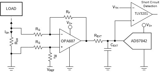
GUID-3D9012BE-D701-440B-A6B1-77B691DD296D-low.gif适用于电流感应应用的 OPAx607
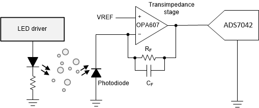
GUID-71027D0A-1668-4E63-AB1E-D2CD81FFF7A4-low.gif适用于跨阻应用的 OPAx607