ZHCSC39B February   2014  – November 2017 DRV8308

PRODUCTION DATA.  

  1. 特性
  2. 应用
  3. 说明
  4. 修订历史记录
  5. Pin Configurations and Functions
  6. Specifications
    1. 6.1 Absolute Maximum Ratings
    2. 6.2 Handling Ratings
    3. 6.3 Recommended Operating Conditions
    4. 6.4 Thermal Information
    5. 6.5 Electrical Characteristics
    6. 6.6 SPI Timing Requirements
    7. 6.7 Typical Characteristics
  7. Detailed Description
    1. 7.1 Overview
    2. 7.2 Functional Block Diagram
    3. 7.3 Feature Description
      1. 7.3.1  Hall Comparators
      2. 7.3.2  FG Amplifier, Comparator, and FG Output
      3. 7.3.3  Enable, Reset, and Clock Generation
      4. 7.3.4  Commutation
        1. 7.3.4.1 120° 3-Hall Commutation
        2. 7.3.4.2 120° Single-Hall Commutation
        3. 7.3.4.3 180° Sine-Wave-Drive Commutation
      5. 7.3.5  Commutation Logic Block Diagram
      6. 7.3.6  Commutation Parameters
      7. 7.3.7  Braking
      8. 7.3.8  Output Pre-Drivers
      9. 7.3.9  Current Limit
      10. 7.3.10 Charge Pump
      11. 7.3.11 5-V Linear Regulator
      12. 7.3.12 Power Switch
      13. 7.3.13 Protection Circuits
        1. 7.3.13.1 VM Undervoltage Lockout (UVLO)
        2. 7.3.13.2 VM Overvoltage (VMOV)
        3. 7.3.13.3 Motor Overcurrent (OCP)
        4. 7.3.13.4 Charge Pump Failure (CPFAIL)
        5. 7.3.13.5 Charge Pump Short (CPSC)
        6. 7.3.13.6 Overtemperature (OTS)
    4. 7.4 Device Functional Modes
      1. 7.4.1 Modes of Speed Input
        1. 7.4.1.1 Clock Frequency Mode
        2. 7.4.1.2 Clock PWM and Internal Register PWM Modes
      2. 7.4.2 Auto Gain and Advance Compensation
      3. 7.4.3 External EEPROM Mode
    5. 7.5 Programming
      1. 7.5.1 Serial Interface
      2. 7.5.2 Serial Data Format
      3. 7.5.3 Programming the OTP Configuration Memory
    6. 7.6 Register Map
      1. 7.6.1 Control Registers
  8. Application and Implementation
    1. 8.1 Application Information
      1. 8.1.1 Internal Speed Control Loop Constraints
      2. 8.1.2 Hall Sensor Configurations and Connections
      3. 8.1.3 FG Amplifier Configurations and Connections
    2. 8.2 Typical Application
      1. 8.2.1 Design Requirements
      2. 8.2.2 Detailed Design Procedure
        1. 8.2.2.1 Motor voltage
        2. 8.2.2.2 Motor Current (Peak and RMS)
        3. 8.2.2.3 Speed Command Method
        4. 8.2.2.4 Required Flutter (Speed Jitter)
        5. 8.2.2.5 Configuration Method
        6. 8.2.2.6 Hall Element Current
        7. 8.2.2.7 Power FET Switching Time
      3. 8.2.3 Application Curves
    3. 8.3 Do's and Don'ts
      1. 8.3.1 RESET and ENABLE Considerations
  9. Power Supply Recommendations
  10. 10Layout
    1. 10.1 Layout Guidelines
    2. 10.2 Layout Example
  11. 11器件和文档支持
    1. 11.1 文档支持
      1. 11.1.1 相关文档
    2. 11.2 接收文档更新通知
    3. 11.3 社区资源
    4. 11.4 商标
    5. 11.5 静电放电警告
    6. 11.6 Glossary
  12. 12机械、封装和可订购信息

封装选项

机械数据 (封装 | 引脚)
散热焊盘机械数据 (封装 | 引脚)
订购信息

特性

  • 三相无刷直流电机控制器
    • 具有可编程增益和滤波器的数字闭环速度控制
  • 通过 10 至 130mA 可配置栅极驱动器驱动 6 个 N 沟道 MOSFET
  • 通过霍尔传感器实现换向
    • 时序可提前/延迟
    • 120° 或 180°正弦电流控制
    • 通过单输入控制电机转速
  • 工作电源电压范围:8.5V 至 32V
  • 灵活的配置方法
    • 读取内部非易失性存储器
    • 读取外部 EEPROM
    • 写入串行外设接口 (SPI)
  • 可配置的电机限流器
  • 针对霍尔传感器的 5V 稳压器
  • 低功耗待机模式
  • 集成过流、过压和过热保护

应用

  • 工业泵、风扇和阀门
  • 白色家电
  • 电动工具和草坪设备
  • 打印机

说明

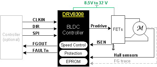
DRV8308 采用高级功能和一个简单的输入接口来 控制 传感器式无刷直流电机作为前置驱动器,它可在 10mA 至 130mA 范围内配置电流以驱动 6 个外部 N 沟道 MOSFET 的栅极,从而实现优异的开关特性。

3 个电机相位根据霍尔传感器输入进行换向。当电机达到稳定速度后,DRV8308 控制器可仅使用 1 个霍尔传感器将传感器失配导致的抖动降至最少。霍尔信号驱动时序可提前或延迟 0.1% 以优化电源效率。可选 180° 换向模式可驱动通过电机的正弦电流,并最大限度减少可闻噪声和转矩波纹。电机峰值电流可通过调整感测电阻进行控制。

DRV8308 控制器实现了闭环速度控制,能够使电机在较宽的负载转矩范围内以精准的转速运转。此系统会将 FG 走线或霍尔传感器生成的电机速度与 CLKIN 引脚的基准频率相匹配。DRV8308 控制器也可利用占空比命令(通过时钟或寄存器设置实现)来驱动电机开环。

DRV8308 具备多重保护 特性, 增强了系统的稳健性,例如可处理并报告过流、过压、低压和过热等故障。

器件信息(1)

器件型号 封装 封装尺寸(标称值)
DRV8308 VQFN (40) 6.00mm x 6.00mm
  1. 如需了解所有可用封装,请参阅数据表末尾的可订购产品附录。

简化的原理图

DRV8308 simple_block.gif