ZHCSD09B September 2014 – October 2015 DLPA2005
PRODUCTION DATA.
- 1 特性
- 2 应用
- 3 说明
- 4 修订历史记录
- 5 Pin Configuration and Functions
- 6 Specifications
-
7 Detailed Description
- 7.1 Overview
- 7.2 Functional Block Diagram
- 7.3
Feature Description
- 7.3.1 DMD Regulators
- 7.3.2 RGB Strobe Decoder
- 7.3.3 LED Current Control
- 7.3.4 Maximum Led Currents and Efficiency Considerations
- 7.3.5 Calculating Inductor Peak Current
- 7.3.6 LED Current Accuracy
- 7.3.7 Transient Current Limiting
- 7.3.8 1.1-V Regulator (Buck Converter)
- 7.3.9 Measurement System
- 7.3.10
Protection Circuits
- 7.3.10.1 Thermal Warning (HOT) and Thermal Shutdown (TSD)
- 7.3.10.2 Low Battery Warning (BAT_LOW) and Undervoltage Lockout (UVLO)
- 7.3.10.3 DMD Regulator Fault (DMD_FLT)
- 7.3.10.4 V6V Power-Good (V6V_PGF) Fault
- 7.3.10.5 VLED Overvoltage (VLED_OVP) Fault
- 7.3.10.6 VLED Power Save Mode
- 7.3.10.7 V1V8 PG Failure
- 7.3.10.8 Interrupt Pin (INTZ)
- 7.3.10.9 SPI
- 7.3.11 Password Protected Registers
- 7.4 Device Functional Modes
- 7.5 Register Maps
- 8 Application and Implementation
- 9 Power Supply Recommendations
- 10Layout
- 11器件和文档支持
- 12机械、封装和可订购信息
8 Application and Implementation
NOTE
Information in the following applications sections is not part of the TI component specification, and TI does not warrant its accuracy or completeness. TI’s customers are responsible for determining suitability of components for their purposes. Customers should validate and test their design implementation to confirm system functionality.
8.1 Application Information
A DLPC343x controller can be used with a DLP2010 (.2 WVGA) DMD or DLP3010 (.3 720p) DMD to provide a compact, reliable, high-efficiency display solution for many different video display applications. The DMDs are spatial light modulators which reflect incoming light from an illumination source to one of two directions with the primary direction being into collection optics within a projection lens. The projection lens sends the light to the destination needed for the application. Each application is derived primarily from the optical architecture of the system and the format of the pixel data being input into the DLPC343x.
In display applications using the DLP2010 DMD or DLP3010 DMD, the DLPA2005 provides all needed analog functions including the analog power supplies and the RGB LED driver to provide a robust and efficient display solution. Display applications of interest include pico-projectors embedded in display devices like smart phones, tablets, cameras, and camcorders. Other applications include wearable (near-eye) displays, battery-powered mobile accessory, interactive display, low latency gaming displays, and digital signage.
Alternately, a DLPC150 controller can be used with a DLP2010 or DLP2010NIR DMD. Applications of interest when using the DLPC150 controller include machine vision systems, spectrometers, skin analysis, medical systems, material identification, chemical sensing, infrared projection, and compressive sensing. In a spectroscopy application the DLPC150 controller and DLP2010NIR DMD are often combined with a single element detector to replace expensive InGaAs array-based detector designs. In this application the DMD acts as a wavelength selector reflecting specific wavelengths of light into the single point detector.
8.2 Typical Projector Application
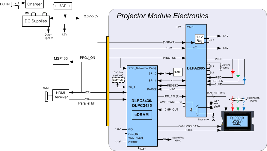
A common application when using DLPA2005 with DLP2010 DMD and DLPC3430/DLPC3435 controller is for creating an accessory projector for a smart phone, tablet or any other portable smart device. The DLPC3430/DLPC3435 in an accessory projector typically receives images from a smart device over either HDMI as shown below (WI-FI can also be used to transmit data). DLPA2005 provides power supply sequencing and controls the RGB LED currents as required by the application.
 Figure 15. Typical Setup Using DLPA2005
8.2.1 Design Requirements
A pico-projector is created by using a DLP chip set comprised of DLP2010 (.2 WVGA) DMD, DLPC3430 or DLPC3435 controller and DLPA2005 PMIC/LED driver. The DLPC3430 or DLPC3435 does the digital image processing, the DLPA2005 provides the needed analog functions for the projector, and DMD is the display device for producing the projected image. In addition to the three DLP chips in the chip set, other chips may be needed. At a minimum a flash part is needed to store the software and firmware to control the DLPC3430 or DLPC3435. The illumination light that is applied to the DMD is typically from red, green, and blue LEDs. These are often contained in three separate packages, but sometimes more than one color of LED die may be in the same package to reduce the overall size of the pico-projector. For connecting the DLPC3430 or DLPC3435 to the front end for receiving images parallel interface is used. While using parallel interface, I2C should be connected to the front end for sending commands to the DLPC3430 or DLPC3435. The only power supplies needed external to the projector are the battery (SYSPWR) and a regulated 1.8 V supply. The entire pico-projector can be turned on and off by using a single signal called PROJ_ON. When PROJ_ON is high, the projector turns on and begins displaying images. When PROJ_ON is set low, the projector turns off and draws just microamps of current on SYSPWR. When PROJ_ON is set low, the 1.8 V supply can continue to be left at 1.8 V and used by other non-projector sections of the product. If PROJ_ON is low, the DLPA2005 will not draw current on the 1.8 V supply.
8.2.2 Detailed Design Procedure
For connecting together the DLP2010, DLPC3430 or DLPC3435 and DLPA2005, see the reference design schematic. When a circuit board layout is created from this schematic a very small circuit board is possible. An example small board layout is included in the reference design data base. Layout guidelines should be followed to achieve a reliable projector. The optical engine that has the LED packages and the DMD mounted to it is typically supplied by an optical OEM who specializes in designing optics for DLP projectors.
8.2.3 Application Curves
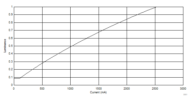
As the LED currents that are driven time-sequentially through the red, green, and blue LEDs are increased, the brightness of the projector increases. This increase is somewhat non-linear, and the curve for typical white screen lumens changes with LED currents. It’s assumed that the same current amplitude is applied to the red, green, and blue LEDs.
 Figure 16. Luminance vs Current
8.3 Typical Mobile Sensing Application
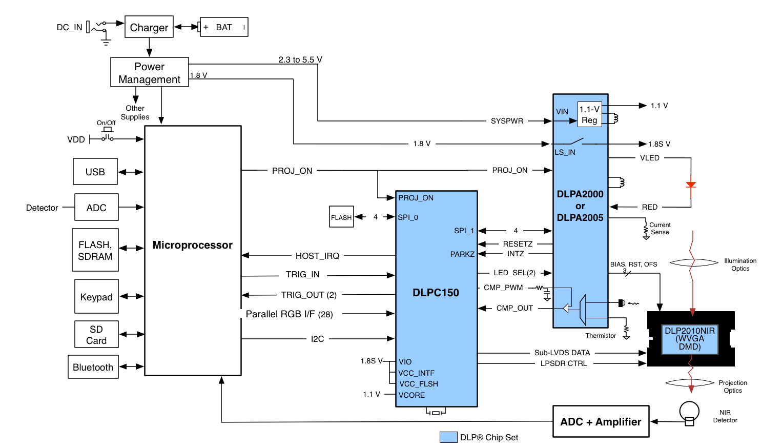
A typical embedded system application using the DLPC150 controller and the DLPC2010NIR is shown in Figure 17. In this configuration, the DLPC150 controller supports a 24-bit parallel RGB input, typical of LCD interfaces, from an external source or processor. The DLPC150 controller processes the digital input image and converts the data into the format needed by the DLP2010NIR. The DLP2010NIR steers light by setting specific micromirrors to the "on" position, directing light to the detector, while unwanted micromirrors are set to "off" position, directing light away from the detector. The microprocessor sends binary images to the DLP2010NIR to steer specific wavelengths of light into the detector. The microprocessor uses an analog-to-digital converter to sample the signal received by the detector into a digital value. By sequentially selecting different wavelengths of light and capturing the values at the detector, the microprocessor can then plot a spectral response to the light.
 Figure 17. Typical Application Diagram
8.3.1 Design Requirements
All applications using the DLP 0.2-inch WVGA chipset require the:
- DLPC150 controller, and
- DLPA2005 PMIC, and
- DLP2010 or DLP2010NIR DMD
- DLPC150 system interfaces:
- Control interface
- Trigger interface
- Input data interface
- Illumination interface
- DLPC150 support circuitry and interfaces:
- Reference clock
- PLL
- Program memory flash interface
- DMD interfaces:
- DLPC150 to DMD digital data
- DLPC150 to DMD control interface
- DLPC150 to DMD micromirror reset control interface
8.3.2 Detailed Design Procedure
8.3.2.1 Dlpc150 System Interfaces
The 0.2-inch WVGA chipset supports a16-bit or 24-bit parallel RGB interface for image data transfers from another device. There are two primary output interfaces: illumination driver control interface and sync outputs.
8.3.2.1.1 Control Interface
The 0.2-inch WVGA chipset supports I2C commands through the control interface. The control interface allows another master processor to send commands to the DLPC150 controller to query system status or perform realtime operations such as LED driver current settings.
8.3.3 Application Curve
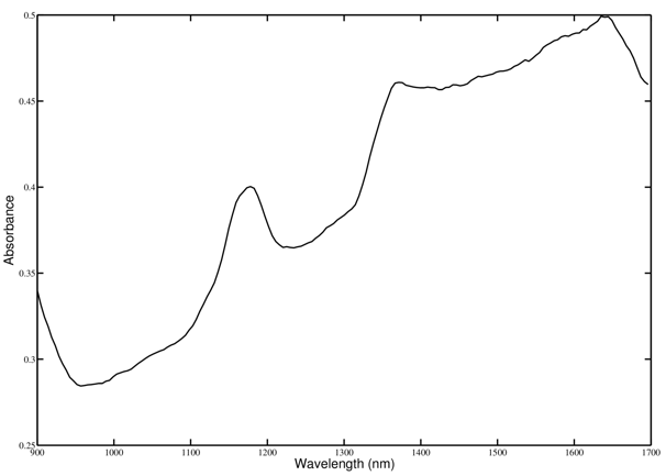
In a reflective spectroscopy application, a broadband light source illuminates a sample and the reflected light spectrum is dispersed onto the DLP2010NIR. A microprocessor in conjunction with the DLPC150 controls individual DLP2010NIR micromirrors to reflect specific wavelengths of light to a single point detector. The microprocessor uses an analog-to-digital converter to sample the signal received by the detector into a digital value. By sequentially selecting different wavelengths of light and capturing the values at the detector, the microprocessor can then plot a spectral response to the light. This systems allows the measurement of the collected light and derive the wavelengths absorbed by the sample. This process leads to the absorption spectrum shown in Figure 18.
 Figure 18. Sample Dlpc150 Based Spectrometer Output