ZHCSJP5B May 2019 – October 2021 ALM2402F-Q1
PRODUCTION DATA
- 1 特性
- 2 应用
- 3 说明
- 4 Revision History
- 5 Pin Configuration and Functions
- 6 Specifications
- 7 Detailed Description
- 8 Application and Implementation
- 9 Power Supply Recommendations
- 10Layout
- 11Device and Documentation Support
- 12Mechanical, Packaging, and Orderable Information
7.3.3 Current-Limit and Short-Circuit Protection
Each op amp in the ALM2402F-Q1 has separate internal current limiting for the PMOS (high-side) and NMOS (low-side) output transistors. If the output is shorted to ground then the PMOS (high-side) current limit is activated, and limits the current to 750 mA nominally. If the output is shorted to supply then the NMOS (low-side) current limit is activated and limits the current to 550 mA nominally at 25°C. The current limit value decreases with increasing temperature as a result of the temperature coefficient of a base-emitter junction voltage. Similarly, the current limit value increases at low temperatures.
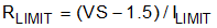
In the case of short-to-ground scenarios, a programmable current limit for the PMOS (high-side) is achieved by adding resistance between VS_O(x), where x = 1 or 2, and the supply VS. The added current limit resistor reduces the drain-source voltage across the PMOS output transistor, thus reducing the output current drive capability. For a desired current limit (ILIMIT), an appropriate current limiting resistor (Rlimit) is selected using Equation 1.
When current is limited, the safe limits for the die temperature must be taken in to account; see the Recommended Operating Conditions and Absolute Maximum Ratings tables. With too much power dissipation, the die temperature can surpass thermal shutdown limits; the op amp shuts down and reactivates after the die has fallen below thermal limits. However, do not continuously operate the device in thermal hysteresis for long periods of time (see the Absolute Maximum Ratings table).