SBOS821 November 2016 TMP421-Q1 , TMP422-Q1 , TMP423-Q1
PRODUCTION DATA.
- 1 Features
- 2 Applications
- 3 Description
- 4 Revision History
- 5 Device Comparison Table
- 6 Pin Configuration and Functions
- 7 Specifications
-
8 Detailed Description
- 8.1 Overview
- 8.2 Functional Block Diagram
- 8.3 Feature Description
- 8.4 Device Functional Modes
- 8.5
Programming
- 8.5.1 Serial Interface
- 8.5.2 Bus Overview
- 8.5.3 Bus Definitions
- 8.5.4 Serial Bus Address
- 8.5.5 Two-Wire Interface Slave Device Addresses
- 8.5.6 Read and Write Operations
- 8.5.7 High-Speed Mode
- 8.5.8 One-Shot Conversion
- 8.5.9 η-Factor Correction Register
- 8.5.10 Software Reset
- 8.5.11 General Call Reset
- 8.5.12 Identification Registers
- 8.6 Register Maps
- 9 Application and Implementation
- 10Power Supply Recommendations
- 11Layout
- 12Device and Documentation Support
- 13Mechanical, Packaging, and Orderable Information
Package Options
Mechanical Data (Package|Pins)
- DCN|8
Thermal pad, mechanical data (Package|Pins)
- DCN|8
Orderable Information
1 Features
- AEC-Q100 Qualified with the Following Results
- Temperature Grade 1: –40°C to +125°C
- Device HBM ESD Classification Level 2
- Device CDM ESD Classification Level C5
- SOT23-8 Package
- ±1°C Remote Diode Sensor (Maximum)
- ±1.5°C Local Temperature Sensor (Maximum)
- Series Resistance Cancellation
- n-Factor Correction
- Two-Wire I2C or SMBus™ Compatible Serial Interface
- Multiple Interface Addresses
- Diode Fault Detection
- RoHS Compliant and No Sb/Br
2 Applications
- Processor and FPGA Temperature Monitoring
- LCD, DLP, and LCOS Projectors
- Servers
- Central Office Telecom Equipment
- Storage Area Networks (SAN)
3 Description
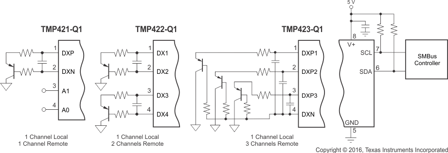
The TMP421-Q1, TMP422-Q1, and TMP423-Q1 devices are single, dual, and triple remote, automotive-qualified temperature sensor monitors with a built-in local temperature sensor. The remote temperature sensor diode-connected transistors are typically low-cost, NPN- or PNP-type transistors or diodes that are an integral part of microcontrollers, microprocessors, or field-programmable gate arrays (FPGAs).
Remote accuracy is ±1°C for multiple device manufacturers, with no calibration needed. The two-wire serial interface accepts SMBus write byte, read byte, send byte, and receive byte commands to configure the device.
The TMP421-Q1, TMP422-Q1, and TMP423-Q1 include series resistance cancellation, programmable non-ideality factor, wide remote temperature
measurement range (up to +150°C), and diode fault detection.
The TMP421-Q1, TMP422-Q1, and TMP423-Q1 are all available in an 8-pin SOT-23 package.
Device Information(1)
| PART NUMBER | PACKAGE | BODY SIZE (NOM) |
|---|---|---|
| TMP421-Q1 TMP422-Q1 TMP423-Q1 |
SOT-23 (8) | 2.90 mm × 1.63 mm |
- For all available packages, see the orderable addendum at the end of the data sheet.
