SBOS745A May 2016 – June 2016 OPT3002
PRODUCTION DATA.
- 1 Features
- 2 Applications
- 3 Description
- 4 Revision History
- 5 Pin Configuration and Functions
- 6 Specifications
- 7 Detailed Description
- 8 Application and Implementation
- 9 Power-Supply Recommendations
- 10Layout
- 11Device and Documentation Support
- 12Mechanical, Packaging, and Orderable Information
Package Options
Mechanical Data (Package|Pins)
- DNP|6
Thermal pad, mechanical data (Package|Pins)
Orderable Information
1 Features
- Wide Optical Spectrum: 300 nm to 1000 nm
- Automatic Full-Scale Setting Feature Simplifies Software and Configuration
- Measurement Levels:
- 1.2 nW/cm2 to 10 mW/cm2
- 23-Bit Effective Dynamic Range With
Automatic Gain Ranging - 12 Binary-Weighted, Full-Scale Range Settings:
< 0.2% (typ) Matching Between Ranges - Low Operating Current: 1.8 µA (typ)
- Operating Temperature: –40°C to +85°C
- Wide Power-Supply: 1.6 V to 3.6 V
- 5.5-V Tolerant I/O
- Flexible Interrupt System
- Small Form Factor: 2.0 mm × 2.0 mm × 0.65 mm
2 Applications
- Intrusion and Door-Open Detection Systems
- System Wake-Up Circuits
- Medical and Scientific Instrumentation
- Display Backlight Controls
- Lighting Control Systems
- Tablet and Notebook Computers
- Thermostats and Home Automation Appliances
- Outdoor Traffic and Street Lights
3 Description
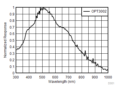
The OPT3002 light-to-digital sensor provides the functionality of an optical power meter within a single device. This optical sensor greatly improves system performance over photodiodes and photoresistors. The OPT3002 has a wide spectral bandwidth, ranging from 300 nm to 1000 nm. Measurements can be made from 1.2 nW/cm2 up to 10 mW/cm2, without the need to manually select the full-scale ranges by using the built-in, full-scale setting feature. This capability allows light measurement over a 23-bit effective dynamic range. The results are compensated for dark-current effects, as well as other temperature variations.
Use the OPT3002 in optical spectral systems that require detection of a variety of wavelengths, such as optically-based diagnostic systems. The interrupt pin system can summarize the result of the measurement with one digital pin. Power consumption is very low, allowing the OPT3002 to be used as a low-power, battery-operated, wake-up sensor when an enclosed system is opened.
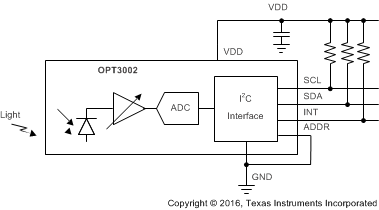
The OPT3002 is fully integrated and provides optical power reading directly from the I2C- and SMBus-compatible, two-wire, serial interface. Measurements are either continuous or single-shot. The OPT3002 fully-operational power consumption is as low as 0.8 µW at 0.8 SPS on a 1.8-V supply.
Device Information(1)
| PART NUMBER | PACKAGE | BODY SIZE (NOM) |
|---|---|---|
| OPT3002 | USON (6) | 2.00 mm x 2.00 mm |
- For all available packages, see the package option addendum at the end of the datasheet.
Spectral Response

Block Diagram
