ZHCSDZ9 July 2015
PRODUCTION DATA.
- 1 特性
- 2 应用
- 3 说明
- 4 修订历史记录
- 5 说明(续)
- 6 Pin Configuration and Functions
-
7 Specifications
- 7.1 Absolute Maximum Ratings
- 7.2 ESD Ratings
- 7.3 Recommended Operating Conditions
- 7.4 Thermal Information
- 7.5 Electrical Characteristics: Supply Current
- 7.6 Electrical Characteristics: Power Supply Control
- 7.7 Electrical Characteristics: AFE Power-On Reset
- 7.8 Electrical Characteristics: AFE Watchdog Reset and Wake Timer
- 7.9 Electrical Characteristics: Current Wake Comparator
- 7.10 Electrical Characteristics: VC1, VC2, VC3, VC4, BAT, PACK
- 7.11 Electrical Characteristics: SMBD, SMBC
- 7.12 Electrical Characteristics: PRES, BTP_INT, DISP
- 7.13 Electrical Characteristics: LEDCNTLA, LEDCNTLB, LEDCNTLC
- 7.14 Electrical Characteristics: Coulomb Counter
- 7.15 Electrical Characteristics: CC Digital Filter
- 7.16 Electrical Characteristics: ADC
- 7.17 Electrical Characteristics: ADC Digital Filter
- 7.18 Electrical Characteristics: CHG, DSG FET Drive
- 7.19 Electrical Characteristics: PCHG FET Drive
- 7.20 Electrical Characteristics: FUSE Drive
- 7.21 Electrical Characteristics: Internal Temperature Sensor
- 7.22 Electrical Characteristics: TS1, TS2, TS3, TS4
- 7.23 Electrical Characteristics: PTC, PTCEN
- 7.24 Electrical Characteristics: Internal 1.8-V LDO
- 7.25 Electrical Characteristics: High-Frequency Oscillator
- 7.26 Electrical Characteristics: Low-Frequency Oscillator
- 7.27 Electrical Characteristics: Voltage Reference 1
- 7.28 Electrical Characteristics: Voltage Reference 2
- 7.29 Electrical Characteristics: Instruction Flash
- 7.30 Electrical Characteristics: Data Flash
- 7.31 Electrical Characteristics: OCD, SCC, SCD1, SCD2 Current Protection Thresholds
- 7.32 Timing Requirements: OCD, SCC, SCD1, SCD2 Current Protection Timing
- 7.33 Timing Requirements: SMBus
- 7.34 Timing Requirements: SMBus XL
- 7.35 Typical Characteristics
-
8 Detailed Description
- 8.1 Overview
- 8.2 Functional Block Diagram
- 8.3
Feature Description
- 8.3.1 Primary (1st Level) Safety Features
- 8.3.2 Secondary (2nd Level) Safety Features
- 8.3.3 Charge Control Features
- 8.3.4 Gas Gauging
- 8.3.5 Configuration
- 8.3.6 Battery Parameter Measurements
- 8.3.7 Battery Trip Point (BTP)
- 8.3.8 Lifetime Data Logging Features
- 8.3.9 Authentication
- 8.3.10 LED Display
- 8.3.11 Voltage
- 8.3.12 Current
- 8.3.13 Temperature
- 8.3.14 Communications
- 8.4 Device Functional Modes
- 9 Applications and Implementation
- 10Power Supply Recommendations
- 11Layout
- 12器件和文档支持
- 13机械、封装和可订购信息
1 特性
- 全集成 1 节、2 节、3 节和 4 节串联锂离子或锂聚合物电池组管理器及保护
- 下一代已获专利的 Impedance Track™ 技术可准确测量锂离子和锂聚合物电池中的可用电量
- 高侧 N 通道保护场效应晶体管 (FET) 驱动
- 充电或者静止状态时集成的电池均衡
- 可编程保护特性的完全阵列
- 电压
- 电流
- 温度
- 充电终止时间
- CHG/DSG FET
- 模拟前端 (AFE)
- 精密的充电算法
- 日本电子与信息技术工业协会 (JEITA)
- 增强型充电
- 自适应充电
- 电池均衡
- 支持 TURBO 升压模式
- 支持电池跳变点 (BTP)
- 诊断寿命数据监视器和黑匣子记录器
- 发光二极管 (LED) 显示
- 支持 2 线制系统管理总线 (SMBus) v1.1 接口
- 安全散列算法 (SHA-1) 认证
- 紧凑封装:32 导线四方扁平无引线 (QFN) (RSM)
2 应用
- 笔记本/上网本
- 医疗与测试设备
- 便携式仪表
3 说明
bq40z50-R1 器件采用已获专利的 Impedance Track™ 技术,是一款基于电池组的单芯片全集成解决方案,针对 1 节、2 节、3 节和 4 节串联锂离子或锂聚合物电池组提供电量监测、保护及认证等一些列丰富的功能。
bq40z50-R1 器件利用其集成的高性能模拟外设,测量锂离子或锂聚合物电池的可用容量、电压、电流、温度和其他关键参数,保留准确的数据记录,并通过 SMBus v1.1 兼容接口将这些信息报告给系统主机控制器。
器件信息(1)
| 器件型号 | 封装 | 封装尺寸(标称值) |
|---|---|---|
| bq40z50-R1 | VQFN (32) | 4.00mm x 4.00mm |
- 如需了解所有可用封装,请见数据表末尾的可订购产品附录。
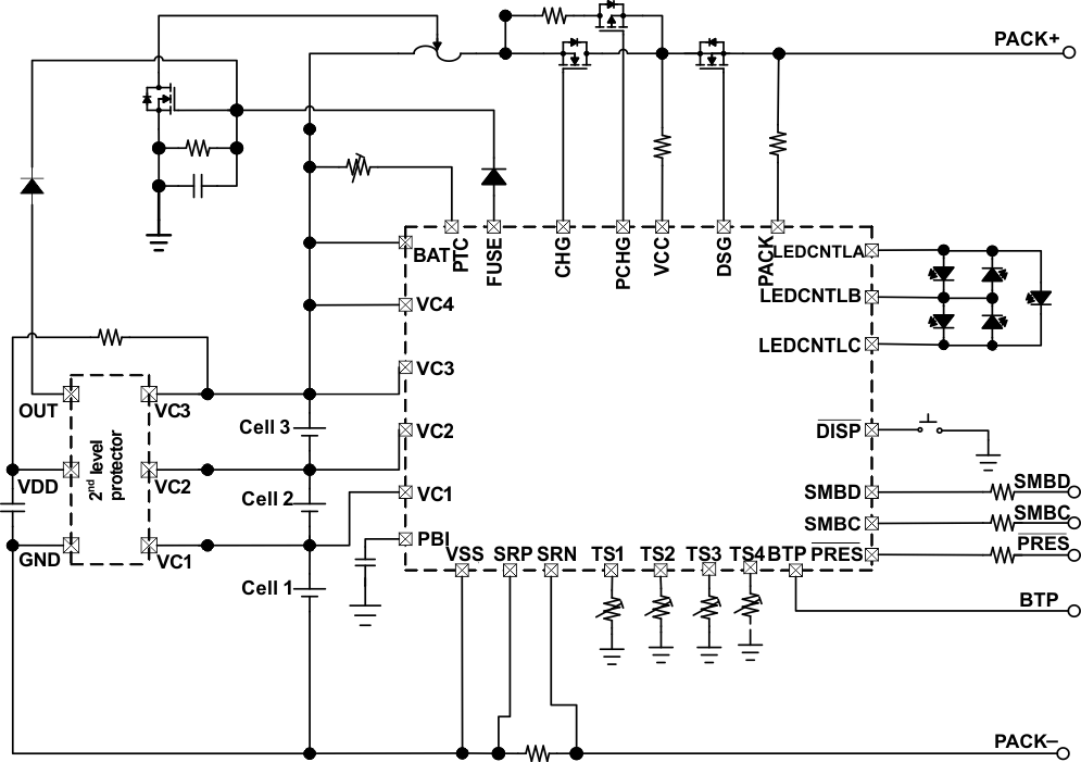
简化电路原理图
