ZHCSAP1D December 2012 – September 2014 TPS43060 , TPS43061
PRODUCTION DATA.
- 1 特性
- 2 应用
- 3 说明
- 4 简化电路原理图
- 5 修订历史记录
- 6 Pin Configuration and Functions
- 7 Specifications
-
8 Detailed Description
- 8.1 Overview
- 8.2 Functional Block Diagram
- 8.3
Feature Description
- 8.3.1 Switching Frequency
- 8.3.2 Low-Dropout Regulator
- 8.3.3 Input Undervoltage (UV)
- 8.3.4 Enable and Adjustable UVLO
- 8.3.5 Voltage Reference and Setting Output Voltage
- 8.3.6 Minimum On-Time and Pulse Skipping
- 8.3.7 Zero-Cross Detection and Duty Cycle
- 8.3.8 Minimum Off-Time and Maximum Duty Cycle
- 8.3.9 Soft-Start
- 8.3.10 Power Good
- 8.3.11 Overvoltage Protection (OVP)
- 8.3.12 OVP and Current Sense Resistor Selection
- 8.3.13 Gate Drivers
- 8.3.14 Thermal Shutdown
- 8.4 Device Functional Modes
-
9 Application and Implementation
- 9.1 Application Information
- 9.2
Typical Applications
- 9.2.1
Synchronous Boost Converter Typical Application Using TPS43061
- 9.2.1.1 Design Requirements
- 9.2.1.2
Detailed Design Procedure
- 9.2.1.2.1 Selecting the Switching Frequency
- 9.2.1.2.2 Inductor Selection
- 9.2.1.2.3 Selecting the Current Sense Resistor
- 9.2.1.2.4 Output Capacitor Selection
- 9.2.1.2.5 MOSFET Selection - NexFET Power Block
- 9.2.1.2.6 Bootstrap Capacitor Selection
- 9.2.1.2.7 VCC Capacitor
- 9.2.1.2.8 Input Capacitor
- 9.2.1.2.9 Output Voltage and Feedback Resistors Selection
- 9.2.1.2.10 Setting the Soft-Start Time
- 9.2.1.2.11 UVLO Set Point
- 9.2.1.2.12 Power Good Resistor Selection
- 9.2.1.2.13 Control Loop Compensation
- 9.2.1.2.14 DCM, Pulse-Skip Mode, and No-Load Input Current
- 9.2.1.3 Application Curves
- 9.2.2 High-Efficiency 40-V Synchronous Boost Converter Typical Application Using TPS43060
- 9.2.1
Synchronous Boost Converter Typical Application Using TPS43061
- 10Power Supply Recommendations
- 11Layout
- 12器件和文档支持
- 13机械、封装和可订购信息
1 特性
- 58V 最大输出电压
- VIN 范围:4.5V 至 38V(绝对最大值为 40V)
- TPS43060:针对标准阈值 MOSFET 优化的 7.5V 栅极驱动器
- TPS43061:针对低 Qg 优化的 5.5V 栅极驱动器 NexFET™功率 MOSFET
- 支持内部斜率补偿的电流模式控制
- 可调频率范围:50kHz 至 1MHz
- 同步外部时钟功能
- 可调软启动时间
- 电感器直流电阻 (DCR) 或电阻器电流感测
- 输出电压电源正常指示器
- ±0.8% 反馈基准电压
- 5µA 关断电源电流
- 600µA 静态工作电流
- 集成引导加载二极管 (TPS43061)
- 逐周期电流限制和热关断
- 可调节的欠压闭锁 (UVLO) 和输出过压保护
- 小型 16 引脚 WQFN (3mm × 3mm) 封装,带有 PowerPAD™
- 运行 TJ范围:–40°C 至 150°C
2 应用
- 用于 PC 的 Thunderbolt 端口
- 汽车电源系统
- 同步回扫
- 氮化镓 (GaN) 射频 (RF) 功率放大器
- 平板笔记本附件
- 电池供电系统
- 5V、12V 和 24V 直流总线电源系统
3 说明
TPS43060 和 TPS43061 是低 IQ 电流模式同步升压控制器,支持 4.5V 至 38V(绝对最大值为 40V)的宽输入电压范围和高达 58V 的升压输出范围。同步整流功能可为高电流 应用实现高效率,无损电感直流电阻 (DCR) 感测功能可进一步提升效率。该器件产生的功率损耗较低,并且采用带 PowerPAD™的 3mm × 3mm WQFN-16 封装,可以在扩展级温度范围(-40°C 至 150°C)内支持高功率密度且高可靠性的升压转换器解决方案。
TPS43060 含有一个 7.5V 栅极驱动电源,适合驱动各种 MOSFET。TPS43061 具有一个 5.5V 栅极驱动电源,驱动强度针对低 Qg NexFET 功率 MOSFET 进行了优化。另外,TPS43061 为高侧栅极驱动器提供了一个集成型自举二极管,从而减少了外部部件数量。
器件信息(1)
| 器件型号 | 封装 | 封装尺寸(标称值) |
|---|---|---|
| TPS43060 | RTE (16) | 3.00mm × 3.00mm |
| TPS43061 |
- 要了解所有可用封装,请见数据表末尾的可订购产品附录。
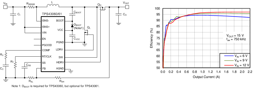
4 简化电路原理图
