SLOS704B January   2011  – August 2015 TPA6138A2

PRODUCTION DATA.  

  1. Features
  2. Applications
  3. Description
  4. Revision History
  5. Device Comparison Table
  6. Pin Configuration and Functions
  7. Specifications
    1. 7.1 Absolute Maximum Ratings
    2. 7.2 ESD Ratings
    3. 7.3 Recommended Operating Conditions
    4. 7.4 Thermal Information
    5. 7.5 Electrical Characteristics
    6. 7.6 Operating Characteristics
    7. 7.7 Typical Characteristics
  8. Parameter Measurement Information
  9. Detailed Description
    1. 9.1 Overview
    2. 9.2 Functional Block Diagram
    3. 9.3 Feature Description
      1. 9.3.1 Direct Path Headphone Driver
    4. 9.4 Device Functional Modes
      1. 9.4.1 Mute Operation
      2. 9.4.2 Using the TPA6138A2 as a Second-Order Filter
      3. 9.4.3 TPA6138A2 UVP Operation
  10. 10Application and Implementation
    1. 10.1 Application Information
      1. 10.1.1 Gain-Setting Resistor Ranges
      2. 10.1.2 Input-Blocking Capacitors
    2. 10.2 Typical Application
      1. 10.2.1 Design Requirements
      2. 10.2.2 Detailed Design Procedure
        1. 10.2.2.1 Charge-Pump Flying Capacitor and VSS Capacitor
        2. 10.2.2.2 Decoupling Capacitors
      3. 10.2.3 Application Curves
  11. 11Power Supply Recommendations
  12. 12Layout
    1. 12.1 Layout Guidelines
      1. 12.1.1 Gain-Setting Resistors
      2. 12.1.2 Decoupling Capacitors Placement
    2. 12.2 Layout Example
  13. 13Device and Documentation Support
    1. 13.1 Device Support
      1. 13.1.1 Development Support
    2. 13.2 Community Resources
    3. 13.3 Trademarks
    4. 13.4 Electrostatic Discharge Caution
    5. 13.5 Glossary
  14. 14Mechanical, Packaging, and Orderable Information

封装选项

机械数据 (封装 | 引脚)
散热焊盘机械数据 (封装 | 引脚)
订购信息

12 Layout

12.1 Layout Guidelines

12.1.1 Gain-Setting Resistors

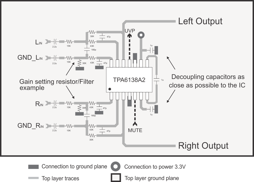
The gain-setting resistors, RIN and Rfb, must be placed close to pins 13 and 17, respectively, to minimize capacitive loading on these input pins and to ensure maximum stability of the TPA6138A2. For the recommended PCB layout, see the TPA6138A2EVM User's Guide (SLOU305).

12.1.2 Decoupling Capacitors Placement

A low equivalent-series-resistance (ESR) ceramic capacitor, typically 1 μF, placed as close as possible to the device VDD lead works best. Placing this decoupling capacitor close to the TPA6138A2 is important for the performance of the amplifier. For filtering lower-frequency noise signals, a 10-μF or greater capacitor placed near the audio power amplifier would also help, but it is not required in most applications because of the high PSRR of this device

12.2 Layout Example
TPA6138A2 Layout_example.gif