ZHCSES8 March   2016 LM5022-Q1

PRODUCTION DATA.  

  1. 特性
  2. 应用
  3. 说明
  4. 修订历史记录
  5. Pin Configuration and Functions
  6. Specifications
    1. 6.1 Absolute Maximum Ratings
    2. 6.2 ESD Ratings: LM5022-Q1
    3. 6.3 Recommended Operating Conditions
    4. 6.4 Thermal Information
    5. 6.5 Electrical Characteristics
    6. 6.6 Typical Characteristics
  7. Detailed Description
    1. 7.1 Overview
    2. 7.2 Functional Block Diagram
    3. 7.3 Feature Description
      1. 7.3.1 High Voltage Start-Up Regulator
      2. 7.3.2 Input Undervoltage Detector
      3. 7.3.3 Error Amplifier
      4. 7.3.4 Current Sensing and Current Limiting
      5. 7.3.5 PWM Comparator and Slope Compensation
      6. 7.3.6 Soft Start
      7. 7.3.7 MOSFET Gate Driver
      8. 7.3.8 Thermal Shutdown
    4. 7.4 Device Functional Modes
      1. 7.4.1 Oscillator, Shutdown, and SYNC
  8. Application and Implementation
    1. 8.1 Application Information
    2. 8.2 Typical Application
      1. 8.2.1 Design Requirements
      2. 8.2.2 Detailed Design Procedure
        1. 8.2.2.1  Switching Frequency
        2. 8.2.2.2  MOSFET
        3. 8.2.2.3  Output Diode
        4. 8.2.2.4  Boost Inductor
        5. 8.2.2.5  Output Capacitor
        6. 8.2.2.6  VCC Decoupling Capacitor
        7. 8.2.2.7  Input Capacitor
        8. 8.2.2.8  Current Sense Filter
        9. 8.2.2.9  RSNS, RS2 and Current Limit
        10. 8.2.2.10 Control Loop Compensation
        11. 8.2.2.11 Efficiency Calculations
          1. 8.2.2.11.1 Chip Operating Loss
          2. 8.2.2.11.2 MOSFET Switching Loss
          3. 8.2.2.11.3 MOSFET and RSNS Conduction Loss
          4. 8.2.2.11.4 Output Diode Loss
          5. 8.2.2.11.5 Input Capacitor Loss
          6. 8.2.2.11.6 Output Capacitor Loss
          7. 8.2.2.11.7 Boost Inductor Loss
          8. 8.2.2.11.8 Total Loss
          9. 8.2.2.11.9 Efficiency
      3. 8.2.3 Application Curves
  9. Power Supply Recommendations
  10. 10Layout
    1. 10.1 Layout Guidelines
      1. 10.1.1 Filter Capacitors
      2. 10.1.2 Sense Lines
      3. 10.1.3 Compact Layout
      4. 10.1.4 Ground Plane and Shape Routing
    2. 10.2 Layout Example
  11. 11器件和文档支持
    1. 11.1 器件支持
      1. 11.1.1 Third-Party Products Disclaimer
      2. 11.1.2 设计支持
    2. 11.2 社区资源
    3. 11.3 商标
    4. 11.4 静电放电警告
    5. 11.5 Glossary
  12. 12机械、封装和可订购信息

封装选项

机械数据 (封装 | 引脚)
散热焊盘机械数据 (封装 | 引脚)
订购信息

1 特性

  • 具有符合 AEC-Q100 1 级标准的下列结果:
    • 器件温度等级 1:-40°C 至 125°C 的环境运行温度范围
    • 器件人体放电模式 (HBM) 静电放电 (ESD) 分类等级 2
    • 器件组件充电模式 (CDM) ESD 分类等级 C5
  • 内部 60V 启动稳压器
  • 峰值电流为 1A 的金属氧化物半导体场效应晶体管 (MOSFET) 栅极驱动器
  • VIN 范围:6V 至 60V(启动后,最低可以在 3V 下工作)
  • 占空比限值为 90%
  • 可编程欠压锁定 (UVLO) 与滞后
  • 逐周期电流限制
  • 可通过单个电阻设置振荡器频率
  • 可调节开关频率范围达 2.2MHz
  • 外部时钟同步
  • 斜率补偿
  • 可调节软启动
  • 10 引脚超薄小外形尺寸 (VSSOP) 封装

2 应用

  • 升压转换器
  • SEPIC 转换器

3 说明

LM5022-Q1 是一款高压、低侧 N 沟道 MOSFET 控制器,非常适合升压稳压器和 SEPIC 稳压器。该器件包含实现 单端 一次侧拓扑所需的全部功能。输出稳压基于电流模式控制,这不仅简化了环路补偿的设计,同时还能够提供固有输入电压前馈。LM5022-Q1 包含一个启动稳压器,该稳压器在 6V 至 60V 的宽输入电压范围内工作。PWM 控制器专为高速性能而设计,振荡器频率范围高达 2.2MHz,总传播延迟不到 100ns。其他 功能 包括误差放大器、精密基准、线路欠压锁定、逐周期电流限制、斜率补偿、软启动、外部同步功能以及热关断。LM5022-Q1 采用 10 引脚 VSSOP 封装。

器件信息(1)

器件型号 封装 封装尺寸(标称值)
LM5022-Q1 VSSOP (10) 3.00mm x 3.00mm
  1. 要了解所有可用封装,请见数据表末尾的可订购产品附录。

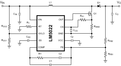
典型应用

LM5022-Q1 20212201.gif