SNIS106Q December 1999 – January 2015 LM20
PRODUCTION DATA.
- 1 Features
- 2 Applications
- 3 Description
- 4 Revision History
- 5 Pin Configuration and Functions
- 6 Specifications
- 7 Detailed Description
- 8 Application and Implementation
- 9 Power Supply Recommendations
- 10Layout
- 11Device and Documentation Support
- 12Mechanical, Packaging, and Orderable Information
5 Pin Configuration and Functions
DCK Package
5-Pin SC70
(Top View)

YZR Package
4-Pin DSBGA
(Top View)
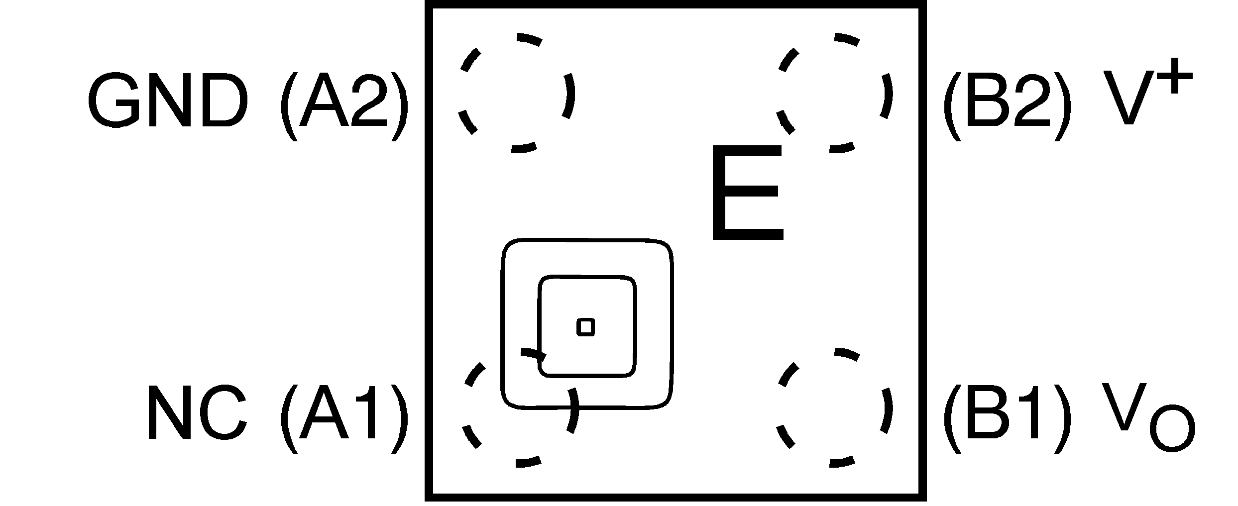
Pin Functions
| PIN | TYPE | DESCRIPTION | ||
|---|---|---|---|---|
| NAME | DSBGA | SC70 | ||
| GND | — | 2 | GND | Device substrate and die attach paddle, connect to power supply negative terminal. For optimum thermal conductivity to the PC board ground plane, pin 2 must be grounded. This pin may also be left floating. |
| GND | A2 | 5 | GND | Device ground pin, connect to power supply negative terminal. |
| NC | A1 | 1 | — | NC (pin 1) must be left floating or grounded. Other signal traces must not be connected to this pin. |
| VO | B1 | 3 | Analog Output | Temperature sensor analog output |
| V+ | B2 | 4 | Power | Positive power supply pin |