SNIS160E May 1999 – February 2015 LM135 , LM135A , LM235 , LM235A , LM335 , LM335A
PRODUCTION DATA.
7 Detailed Description
7.1 Overview
Applications for the LM135 include almost any type of temperature sensing over a −55°C to 150°C temperature range. The low impedance and linear output make interfacing to readout or control circuitry especially easy.
The LM135 operates over a −55°C to 150°C temperature range while the LM235 operates over a −40°C to 125°C temperature range. The LM335 operates from −40°C to 100°C.
Operating as a 2-terminal zener, the LM135 has a breakdown voltage directly proportional to absolute temperature at 10 mV/°K. With less than 1-Ω dynamic impedance, the device operates over a current range of 400 μA to 5 mA with virtually no change in performance. When calibrated at 25°C, the LM135 has typically less than 1°C error over a 100°C temperature range. Unlike other sensors, the LM135 has a linear output.
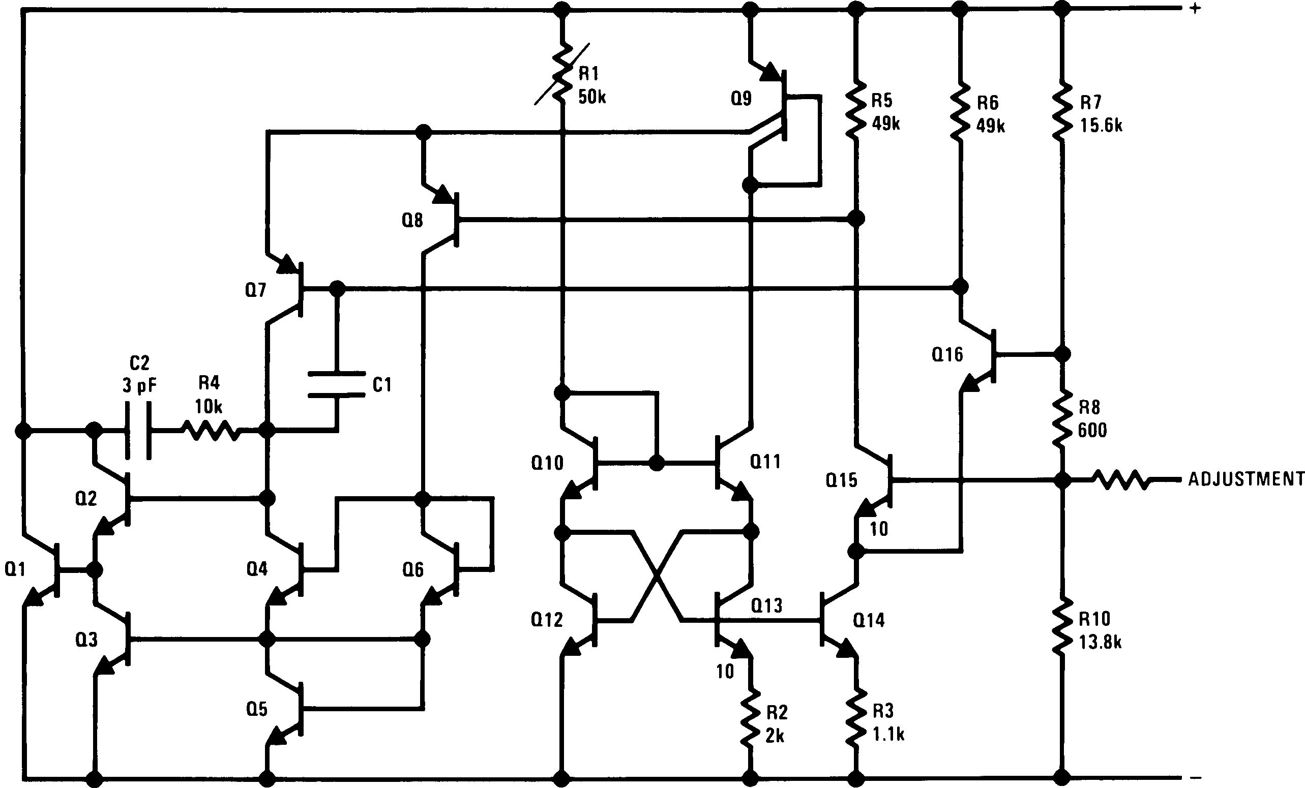
7.2 Functional Block Diagram
7.3 Feature Description
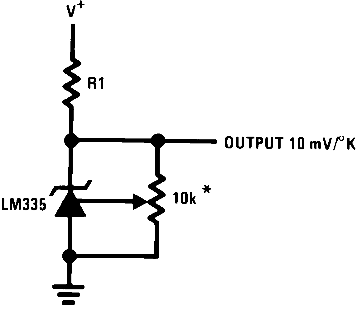
7.3.1 Temperature Calibration Using ADJ Pin
Included on the LM135 chip is an easy method of calibrating the device for higher accuracies. A pot connected across the LM135 with the arm tied to the adjustment terminal (as shown in Figure 12) allows a 1-point calibration of the sensor that corrects for inaccuracy over the full temperature range.
This single point calibration works because the output of the LM135 is proportional to absolute temperature with the extrapolated output of sensor going to 0-V output at 0 K (−273.15°C). Errors in output voltage versus temperature are only slope (or scale factor) errors so a slope calibration at one temperature corrects at all temperatures.
The output of the device (calibrated or uncalibrated) can be expressed as:
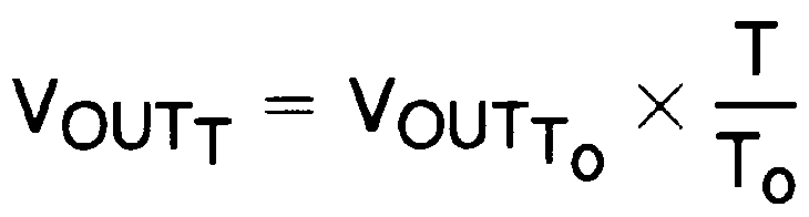
where
- T is the unknown temperature in degrees Kelvin
- To is a reference temperature in degrees Kelvin
By calibrating the output to read correctly at one temperature the output at all temperatures is correct. Nominally the output is calibrated at 10 mV/K.
7.4 Device Functional Modes
The LM135 has two functional modes calibrated and uncalibrated. For optimum accuracy, a one point calibration is recommended. For more information on calibration, see Temperature Calibration Using ADJ Pin.