ZHCSCR2 July 2014
PRODUCTION DATA.
- 1 特性
- 2 应用
- 3 说明
- 4 简化电路原理图
- 5 修订历史记录
- 6 说明(续)
- 7 Pin Configuration and Functions
-
8 Specifications
- 8.1 Absolute Maximum Ratings
- 8.2 Handling Ratings
- 8.3 Recommended Operating Conditions
- 8.4 Thermal Information
- 8.5 Electrical Characteristics: Supply Current
- 8.6 Electrical Characteristics: I/O
- 8.7 Electrical Characteristics: ADC
- 8.8 Electrical Characteristics: Power-On Reset
- 8.9 Electrical Characteristics: Oscillator
- 8.10 Electrical Characteristics: Data Flash Memory
- 8.11 Electrical Characteristics: Register Backup
- 8.12 SMBus Timing Specifications
- 8.13 Typical Characteristics
- 9 Detailed Description
- 10Application and Implementation
- 11Power Supply Recommendations
- 12Layout
- 13器件和文档支持
- 14机械封装和可订购信息
10 Application and Implementation
10.1 Application Information
The bq78350 Battery Management Controller companion to the bq769x0 family of battery monitoring AFEs enables many standard and enhanced battery management features in a 3-series to 15-series Li-Ion/Li Polymer battery pack.
To design and implement a complete solution, users need the Battery Management Studio (bqSTUDIO) tool to configure a "golden image" set of parameters for a specific battery pack and application. The bqSTUDIO tool is a graphical user-interface tool installed on a PC during development. The firmware installed in the product has default values, which are summarized in the bq78350 Technical Reference Manual (SLUUAN7). With the bqSTUDIO tool, users can change these default values to cater to specific application requirements. Once the system parameters are known (for example, fault trigger thresholds for protection, enable/disable of certain features for operation, configuration of cells, among others), the data can be saved. This data is referred to as the "golden image.”
10.2 Typical Applications
The bq78350 can be used with the bq76920, bq76930, or bq76940 device, but as default it is setup for a 5-series cell, 4400-mA battery application using the bq76920 AFE.
10.2.1 Schematic
The schematic is split into two sections: the gas gauge section (Figure 8) and the AFE section (Figure 9).
 Figure 8. 5-Series Cell Typical Schematic, Gas Gauge (bq78350)
 Figure 9. 5-Series Cell Typical Schematic, AFE (bq76920)
10.2.2 Design Requirements
Table 1 lists the device's default settings and feature configurations when shipped from Texas Instruments.
Table 1. TI Default Settings
| Design Parameter | Value or State |
|---|---|
| Cell Configuration | 5s2p (5-series with 1 Parallel) |
| Design Capacity | 4400 mAh |
| Device Chemistry | Chem ID 1210 (LiCoO2/graphitized carbon) |
| Cell Overvoltage (per cell) | 4250 mV |
| Cell Undervoltage (per cell) | 2500 mV |
| Overcurrent in CHARGE Mode | 6000 mA |
| Overcurrent in DISCHARGE Mode | –6000 mA |
| Over Load Current | 0.017 V/Rsense across SRP, SRN |
| Short Circuit in DISCHARGE Mode | 0.44 V/Rsense across SRP, SRN |
| Over Temperature in CHARGE Mode | 55°C |
| Over Temperature in DISCHARGE Mode | 55°C |
| SAFE Pin Activation Enabled | No |
| Safety Over Voltage (per cell) | 4400 mV |
| Safety Under Voltage (per cell) | 2500 mV |
| Shutdown Voltage | 2300 mV |
| Cell Balancing Enabled | Yes |
| Internal or External Temperature Sensor | External Enabled |
| SMB BROADCAST Mode | Disabled |
| Display Mode (# of Bars and LED or LCD) | 5-bar LED |
| Dynamic SMB Address Enabled | No (SMB Address = 0x16) |
| KEYIN Feature Enabled | No |
| PRES Feature Enabled | No |
10.2.3 Detailed Design Procedure
By default, the bq78350 is initially setup to keep the CHG, DSG, and PCHG FETs OFF and many other features disabled until the appropriate ManufacturingStatus() bit that enables ManufacturerAccess() commands are received, or when the default Manufacturing Status is changed.
In the first steps to evaluating the bq78350 and bq769x0 AFE, use the ManufacturerAccess() commands to ensure correct operation of features, and if they are needed in the application. Then enable features' reading for more in-depth application evaluation.
Prior to using the bq78350, the default settings should be evaluated as the device has many configuration settings and options. These can be separated into five main areas:
- Measurement System
- Gas Gauging
- Charging
- Protection
- Peripheral Features
The key areas of focus are covered in the following sections.
10.2.3.1 Measurement System
10.2.3.1.1 Cell Voltages
The bq78350 is required to be configured in the AFE Cell Map register to determine which cells to measure based on the physical connections to the bq76920 AFE. The cell voltage data is available through CellVoltage1()…CellVoltage5(). The cell voltages are reported as they are physically stacked. For example, if the device is configured for 3-series cells connected to VC1, VC2, and VC5 per the AFE Cell Map, then the cell voltages are still reported via CellVoltage1(), CellVoltage2(), and CellVoltage3(), respectively.
For improved accuracy, offset calibration is available for each of these values and can be managed through the bqSTUDIO tool. The procedure for calibration is described in the bq78350 Technical Reference Manual (SLUUAN7) in the "Calibration" chapter.
10.2.3.1.2 External Average Cell Voltage
This is enabled by default (DA Configuration [ExtAveEN] = 1) and uses the external resistor divider connected to the VEN and BAT pins to determine the average cell voltage of the battery pack. The average cell voltage is available through ExtAveCellVoltage().
CAUTION
Care should be taken in the selection of the resistor and FETs used in this divider circuit as the tolerance and temperature drift of these components can cause increased measurement error and a gas gauging error if CEDV Gauging Config [ExtAveCell] = 1 (default = 1).
For improved accuracy, offset and Gain calibration is available for this value and can be managed through the bqSTUDIO tool. The procedure for calibration is described in the bq78350 Technical Reference Manual (SLUUAN7) in the "Calibration" chapter.
10.2.3.1.3 Current
Current data is taken from the bq76920 and made available through Current(). The selection of the current sense resistor connected to SRP and SRN of the bq76920 is very important and there are several factors involved.
The aim of the sense resistor selection is to use the widest ADC input voltage range possible.
To maximize accuracy, the sense resistor value should be calculated based on the following formula:
NOTE
RSNS(min) should include tolerance, temperature drift over the application temperature, and PCB layout tolerances when selecting the actual nominal resistor value.
When selecting the RSNS value, be aware that when selecting a small value, for example, 1 mΩ, then the resolution of the current measurement will be > 1 mA. In the example of RSNS = 1 mΩ, the current LSB will be 8.44 mA.
For improved accuracy, offset and gain calibration are available for this value and can be managed through the bqSTUDIO tool. The procedure for calibration is described in the bq78350 Technical Reference Manual (SLUUAN7) in the "Calibration" chapter.
10.2.3.1.4 Temperature
By default, the 78350 uses an external negative temperature coefficient (NTC) thermistor connected to the bq76920 as the source for the Temperature() data. The measurement uses a polynomial expression to transform the bq76920 ADC measurement into 0.1°C resolution temperature measurement. The default polynomial coefficients are calculated using the Semitec 103AT, although other resistances and manufacturers can be used.
To calculate the External Temp Model coefficients, use the bq78350 Family Thermistor Coefficient Calculator shown in the application note, Using the bq78350 (SLUA726).
For improved accuracy, offset calibration is available for this value and can be managed through the bqSTUDIO tool. The procedure for calibration is described in the bq78350 Technical Reference Manual (SLUUAN7) in the "Calibration" chapter.
10.2.3.2 Gas Gauging
The default battery chemistry (Chem ID) is 1210, which is a Li-CoO2 type chemistry. Other secondary Li-Ion based Chem IDs can be obtained from MathCAD Chemistry Selection Tool (SLUC138).
The default maximum capacity of the battery is 4400 mAh and this should be changed based on the cell and battery configuration chosen.
QMAX = Design Capacity of the Cell × # of parallel cells
Where: Design Capacity of the Cell can be taken from the manufacturer data sheet.
The CEDV gas gauging algorithm requires seven coefficients to enable accurate gas gauging. The default values are generic for Li-CoO2 chemistry, but for accurate gas gauging these coefficients should be re-calculated. The procedure to gather the required data and generate the coefficients can be found at http://www.ti.com/tool/GAUGEPARCAL.
10.2.3.3 Charging
The charging algorithm in the bq78350 is configured to support Constant Voltage/Constant Current (CC/CV) charging of a nominal 18-V, 4400-mAh battery.
10.2.3.3.1 Fast Charging Voltage
The charging voltage is configured (Fast Charging: Voltage) based on an individual cell basis (for example, 4200 mV), but the ChargingVoltage() is reported as the required battery voltage (for example, 4200 mV × 5 = 21000 mV).
10.2.3.3.2 Fast Charging Current
The fast charging current is configured to 2000 mA (Fast Charging: Current) by default, which is conservative for the majority of 4400-mAh battery applications. This should be configured based on the battery configuration, cell manufacturer's data sheet, and system power design requirements.
10.2.3.3.3 Other Charging Modes
The bq78350 is configured to limit, through external components, and report either low or 0 ChargingVoltage() and ChargingCurrent(), based on temperature, voltage, and fault status information.
The "Charge Algorithm" section of the bq78350 Technical Reference Manual (SLUUAN7) details these features and settings.
10.2.3.4 Protection
The safety features and settings of the bq78350 are configured conservatively and are suitable for bench evaluation. However, in many cases, users will need to change these values to meet system requirements. These values should not be changed to exceed the safe operating limits provided by the cell manufacturer and any industry standard.
For details on the safety features and settings, see the "Protections" and "Permanent Fail" sections of the bq78350 Technical Reference Manual (SLUUAN7).
10.2.3.5 Peripheral Features
10.2.3.5.1 LED Display
The bq78350 is configured by default to display up to five LEDs in a bar graph configuration based on the value of RemainingStateOfCharge() (RSOC). Each LED represents 20% of RSOC and is illuminated when the bq78350 DISP pin transitions low, and remains on for a programmable period of time.
In addition to many other options, the number of LEDs used and the percentage at which they can be illuminated are configurable.
10.2.3.5.2 SMBus Address
Although the SMBus slave address is a configurable value in the bq78350, this feature is disabled by default and the slave address is 0x16. The SMBus Address feature can allow up to nine different addresses based on external resistor value variation per address.
The default setup of the bq78350 is generic, but there are many additional features that can be enabled and configured to support a variety of system requirements. These are detailed in the bq78350 Technical Reference Manual (SLUUAN7).
10.2.4 Application Performance Plots
When the bq78350 is powered up, there are several signals that are enabled at the same time. Figure 10 shows the rise time of each of the applicable signals.
 Figure 10. VCC, MRST, VEN, and PWRM Upon Power Up
The bq78350 takes a short period of time to boot up before the device can begin updating battery parameter data that can be then reported via the SMBus or the optional display. Normal operation after boot-up is indicated by the VEN pin pulsing to enable voltage data measurements for the ExtAveCell( ) function. Figure 11 shows the timing of these signals.
 Figure 11. Valid VCC to Full FW Operation
Figure 12, Figure 13, Figure 14, and Figure 15 show Measurement System Performance Data of the bq78350 + the bq76920 EVM. This data was taken using a standard bq76920 EVM with power supplies providing the voltage and current reference inputs.
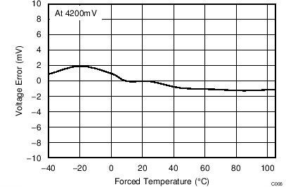 Figure 12. Cell Voltage Error Reported Through CellVoltage1…5()
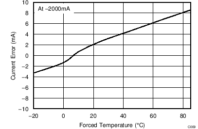 Figure 14. Battery Discharge Current Error Reported Through Current()
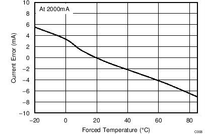 Figure 13. Battery Charge Current Error Reported Through Current()
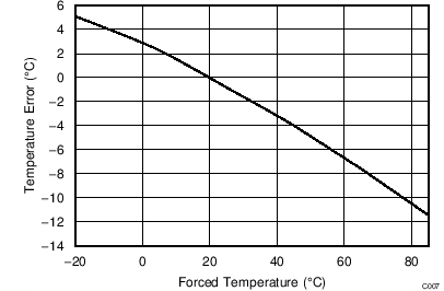 Figure 15. Battery Temperature (External) Error Reported Through Temperature()