ZHCSCA4B January 2014 – June 2014
PRODUCTION DATA.
- 1 特性
- 2 应用范围
- 3 说明
- 4 简化图表
- 5 修订历史记录
- 6 Pin Configuration and Functions
- 7 Specifications
-
8 Detailed Description
- 8.1 Overview
- 8.2 Functional Block Diagram
- 8.3
Feature Description
- 8.3.1 A6 Coil Specification
- 8.3.2 EMI Shield
- 8.3.3 I2C Interface
- 8.3.4 Active or Passive Wake-up State
- 8.3.5 Smart Key or Immobilizer Handling
- 8.3.6 Option Select Pins
- 8.3.7 LED Modes
- 8.3.8 Foreign Object Detection (FOD) and Parasitic Metal Object Detect (PMOD) CalibrationForeign Object Detection (FOD) and Parasitic Metal Object Detect (PMOD) Calibration description.
- 8.3.9 Shut Down via External Thermal Sensor or Trigger
- 8.3.10 Fault Handling and Indication
- 8.3.11 Power Transfer Start Signal
- 8.3.12 Power-On Reset
- 8.3.13 External Reset, RESET Pin
- 8.3.14 Trickle Charge and CS100
- 8.3.15 Over-Voltage Protection Over-Voltage Protection section.
- 8.4 Device Functional Modes
- 9 Applications and Implementation
- 10Power Supply Recommendations
- 11Layout
- 12器件和文档支持
- 13机械封装和可订购信息
2 应用范围
- WPC 1.1 无线充电器:
- 汽车和其他车辆配件内的应用
- 符合 Qi 标准的智能手机和其它手持设备
- 工业和医疗应用
- TI 无线充电解决方案的更多信息,请见www.ti.com.cn/wirelesspower
3 说明
bq500414Q 是一款符合 AEC-Q100 标准的自由定位数字无线电源控制器,此控制器设计用于汽车应用。 它集成了无线电源至 WPC 兼容接收器传输控制所需的全部功能。 它可使用 WPC v1.1 版本,并且针对 12V 系统而设计;然而,bq500414Q 适用于其他电源电压。 bq500414Q 询问 周围环境中将被充电的 WPC 兼容器件。 一旦检测到 WPC 兼容器件,bq500414Q 会立即从被充电器件读取数据包反馈并管理电源传输。 70mm x 20mm 的充电区域在一个发射器垫上提供灵活的接收器放置位置。 bq500414Q 通过持续监视系统已发出和已接收的功率来支持寄生金属物体检测 (PMOD) 和外来物体检测 (FOD),从而保护器件不会出现过热问题。 如果在电源传输期间有任何异常情况发生,bq500414Q 对其进行处理并提供故障指示器输出。 综合保护特性提供稳健耐用设计以保护所有接收器放置位置情况下的系统。
bq500414Q 采用节省空间的 48 引脚,7mm x 7mm 超薄型四方扁平无引线 (VQFN) 封装,运行温度范围介于 -40°C 至 85°C 之间。
器件信息(1)
| 器件名称 | 封装 | 封装尺寸 |
|---|---|---|
| bq500414Q | VQFN (48) | 7mm x 7mm |
- 要了解所有可用封装,请见数据表末尾的可订购产品附录。
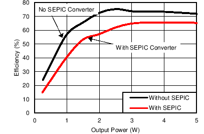
4 简化图表
使用 A6 Tx 线圈时,效率与系统输出功率之间的关系