SBAS585A September   2012  – January 2016 AMC1200-Q1

PRODUCTION DATA.  

  1. Features
  2. Applications
  3. Description
  4. Revision History
  5. Pin Configurations and Functions
  6. Specifications
    1. 6.1 Absolute Maximum Ratings
    2. 6.2 ESD Ratings
    3. 6.3 Recommended Operating Conditions
    4. 6.4 Thermal Information
    5. 6.5 Electrical Characteristics
    6. 6.6 Typical Characteristics
  7. Detailed Description
    1. 7.1 Overview
    2. 7.2 Functional Block Diagram
    3. 7.3 Feature Description
      1. 7.3.1 Insulation Characteristics
      2. 7.3.2 IEC Safety Limiting Values
      3. 7.3.3 Package Characteristics
      4. 7.3.4 Regulatory Information
      5. 7.3.5 Analog Input
    4. 7.4 Device Functional Modes
  8. Application and Implementation
    1. 8.1 Application Information
    2. 8.2 Typical Applications
      1. 8.2.1 Traction Inverter
        1. 8.2.1.1 Design Requirements
        2. 8.2.1.2 Detailed Design Procedure
        3. 8.2.1.3 Application Curves
      2. 8.2.2 Isolated Voltage Measurement
  9. Power Supply Recommendations
  10. 10Layout
    1. 10.1 Layout Guidelines
    2. 10.2 Layout Example
  11. 11Device and Documentation Support
    1. 11.1 Documentation Support
      1. 11.1.1 Related Documentation
    2. 11.2 Community Resources
    3. 11.3 Trademarks
    4. 11.4 Electrostatic Discharge Caution
    5. 11.5 Glossary
  12. 12Mechanical, Packaging, and Orderable Information

封装选项

机械数据 (封装 | 引脚)
散热焊盘机械数据 (封装 | 引脚)
订购信息

10 Layout

10.1 Layout Guidelines

A layout recommendation showing the critical placement of the decoupling capacitors placed as close as possible to the AMC1200-Q1 and maintaining a differential routing of the input signals is shown in Figure 37.

To maintain the isolation barrier and the high CMTI of the device, the distance between the high-side ground (GND1) and the low-side ground (GND2) must be kept at maximum; that is, the entire area underneath the device must be kept free of any conducting materials.

10.2 Layout Example
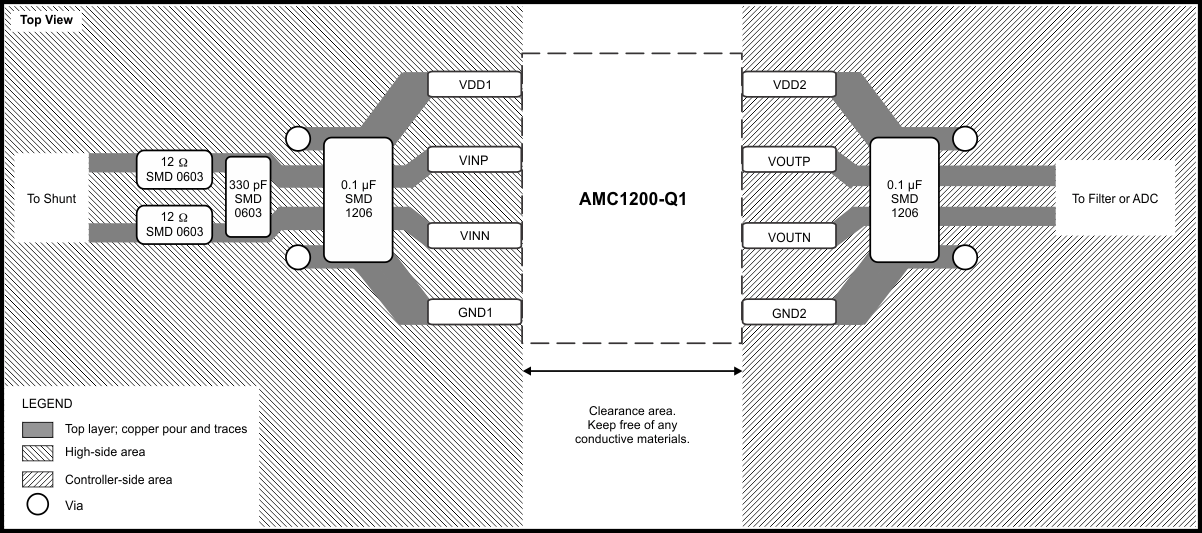
AMC1200-Q1 ai_layout_SBAS585.gif Figure 37. Layout Recommendation