ZHCSFI7 September   2016 TPS2552D , TPS2553D

PRODUCTION DATA.  

  1. 特性
  2. 应用
  3. 说明
  4. 修订历史记录
  5. Device Comparison Table
  6. Pin Configuration and Functions
  7. Specifications
    1. 7.1 Absolute Maximum Ratings
    2. 7.2 ESD Ratings
    3. 7.3 Recommended Operating Conditions
    4. 7.4 Thermal Information
    5. 7.5 Electrical Characteristics
    6. 7.6 Typical Characteristics
  8. Parameter Measurement Information
  9. Detailed Description
    1. 9.1 Overview
    2. 9.2 Functional Block Diagram
    3. 9.3 Feature Description
      1. 9.3.1 Overcurrent Conditions
      2. 9.3.2 Reverse-Voltage Protection
      3. 9.3.3 FAULT Response
      4. 9.3.4 Undervoltage Lockout (UVLO)
      5. 9.3.5 ENABLE
      6. 9.3.6 Thermal Sense
    4. 9.4 Device Functional Modes
    5. 9.5 Programming
      1. 9.5.1 Programming the Current-Limit Threshold
  10. 10Application and Implementation
    1. 10.1 Application Information
      1. 10.1.1 Constant-Current and Impact on Output Voltage
    2. 10.2 Typical Applications
      1. 10.2.1 Two-Level Current-Limit Circuit
        1. 10.2.1.1 Design Requirements
        2. 10.2.1.2 Detailed Design Procedures
          1. 10.2.1.2.1 Designing Above a Minimum Current Limit
          2. 10.2.1.2.2 Designing Below a Maximum Current Limit
          3. 10.2.1.2.3 Accounting for Resistor Tolerance
          4. 10.2.1.2.4 Input and Output Capacitance
        3. 10.2.1.3 Application Curves
      2. 10.2.2 Auto-Retry Functionality
        1. 10.2.2.1 Design Requirements
        2. 10.2.2.2 Detailed Design Procedure
      3. 10.2.3 Typical Application as USB Power Switch
        1. 10.2.3.1 Design Requirements
          1. 10.2.3.1.1 USB Power-Distribution Requirements
        2. 10.2.3.2 Detailed Design Procedure
          1. 10.2.3.2.1 Universal Serial Bus (USB) Power-Distribution Requirements
  11. 11Power Supply Recommendations
    1. 11.1 Self-Powered and Bus-Powered Hubs
    2. 11.2 Low-Power Bus-Powered and High-Power Bus-Powered Functions
    3. 11.3 Power Dissipation and Junction Temperature
  12. 12Layout
    1. 12.1 Layout Guidelines
    2. 12.2 Layout Example
  13. 13器件和文档支持
    1. 13.1 器件支持
    2. 13.2 相关链接
    3. 13.3 接收文档更新通知
    4. 13.4 社区资源
    5. 13.5 商标
    6. 13.6 静电放电警告
    7. 13.7 Glossary
  14. 14机械、封装和可订购信息

封装选项

机械数据 (封装 | 引脚)
散热焊盘机械数据 (封装 | 引脚)
订购信息

特性

  • 最大负载电流可达 1.5A
  • 1.7A 电流下的电流限制精度为 ±6%(典型值)
  • 满足 USB 限流要求
  • 与 TPS2550/51 向后兼容
  • 可调电流限制值,75mA-1700mA(典型值)
  • 恒流(TPS2552D 和 TPS2553D)
  • TPS2552D(支持低电流)和 TPS2553D(支持高电流)
  • 快速过流响应 - 2μs(典型值)
  • 85mΩ 高侧金属氧化物半导体场效应晶体管 (MOSFET)(DBV 封装)
  • 反向输入-输出电压保护
  • 工作范围:2.7V 至 6.5V
  • 内置软启动
  • 15kV ESD 保护,符合 IEC 61000-4-2 标准(带外部电容)
  • UL列表 - 文件号E169910 和 NEMKO IEC60950-1-am1 ed2.0
  • 请见TI 开关系列产品

应用

  • USB 端口/集线器
  • 数字电视
  • 机顶盒
  • 网络语音 (VOIP) 电话

说明

TPS2552D 和 TPS2553D 配电开关专门用于 电流 限制精度有要求或者会遇到重电容负载和短路的应用,并可提供高达 1.5A 的持续负载电流。这些器件借助一个外部电阻器提供一个 75mA至 1.7A(典型值)间的可编程电流限制阈值。在更高电流限制设置上可实现严格至 ±6% 的电流限制精度。对电源开关的上升和下降次数进行控制以大大降低接通/切断期间的电流冲击。

当输出负载超过电流限制阈值时,TPS2552D/3D 器件会通过使用恒流模式将输出电流限制到安全水平。当输出电压被驱动至高于输入电压时,内部反向电压比较器将禁用电源开关以保护此开关输入端的器件。在过流和反向电压情况下,FAULT 输出被置为低电平。

器件信息(1)

器件型号 封装 封装尺寸(标称值)
TPS2552D SOT-23 (6) 2.90mm x 1.60mm
TPS2553D SOT-23 (6) 2.90mm x 1.60mm
  1. 要了解所有可用封装,请见数据表末尾的可订购产品附录。

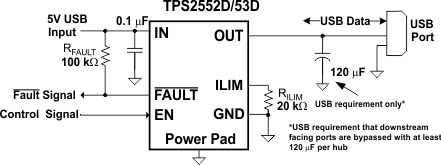
简化电路原理图

TPS2552D TPS2553D typ_app_usb_slvsdl7.gif