SNVS353F February   2005  – September 2016 LM2753

PRODUCTION DATA.  

  1. Features
  2. Applications
  3. Description
  4. Revision History
  5. Pin Configuration and Functions
  6. Specifications
    1. 6.1 Absolute Maximum Ratings
    2. 6.2 ESD Ratings
    3. 6.3 Recommended Operating Conditions
    4. 6.4 Thermal Information
    5. 6.5 Electrical Characteristics
    6. 6.6 Typical Characteristics
  7. Detailed Description
    1. 7.1 Overview
    2. 7.2 Functional Block Diagram
    3. 7.3 Feature Description
      1. 7.3.1 Soft Start
      2. 7.3.2 Flash LED Selection
      3. 7.3.3 PFM Regulation
      4. 7.3.4 Output Voltage Ripple
      5. 7.3.5 IOUT Pin
        1. 7.3.5.1 Setting Flash Current
        2. 7.3.5.2 Setting Torch Current
      6. 7.3.6 PWM Brightness Control Procedures
      7. 7.3.7 Multi-Level Switch Array
      8. 7.3.8 Thermal Protection
      9. 7.3.9 Power Efficiency
    4. 7.4 Device Functional Modes
      1. 7.4.1 Enable Mode
      2. 7.4.2 Flash Mode
  8. Application and Implementation
    1. 8.1 Application Information
    2. 8.2 Typical Application
      1. 8.2.1 Design Requirements
      2. 8.2.2 Detailed Design Procedure
        1. 8.2.2.1 Capacitors
        2. 8.2.2.2 Power Dissipation
      3. 8.2.3 Application Curves
  9. Power Supply Recommendations
  10. 10Layout
    1. 10.1 Layout Guidelines
    2. 10.2 Layout Example
  11. 11Device and Documentation Support
    1. 11.1 Device Support
      1. 11.1.1 Third-Party Products Disclaimer
    2. 11.2 Documentation Support
      1. 11.2.1 Related Documentation
    3. 11.3 Receiving Notification of Documentation Updates
    4. 11.4 Community Resources
    5. 11.5 Trademarks
    6. 11.6 Electrostatic Discharge Caution
    7. 11.7 Glossary
  12. 12Mechanical, Packaging, and Orderable Information

封装选项

机械数据 (封装 | 引脚)
散热焊盘机械数据 (封装 | 引脚)
订购信息

1 Features

  • Input Voltage Range: 3 V to 5.5 V
  • Regulated 5-V Output
  • 250-mA Output Current With a 3.6-V Input
  • 400-mA Pulsed Output Current
    (up to 500-ms Duration)
  • 60-µA (Typical) Quiescent Current
  • Pulse-Frequency Modulation (PFM) Regulation
  • Inductor-Less Solution: Requires Only Three Small Capacitors
  • < 1-µA Typical Shutdown Current
  • 10-pin WSON Package (No Pullback):
    • 3 mm × 3 mm × 0.8 mm

2 Applications

  • Cell-Phone Camera Flash
  • Digital Still Cameras
  • Fire-Alarm Notification
  • Emergency Strobe Lighting
  • Intruder Alert Notification
  • Barcode Scanners
  • Handheld Data Terminals
  • General-Purpose Regulated Voltage Output, High-Current Supply

3 Description

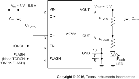
The LM2753 is capable of driving a flash LED with a pulsed current of 400 mA at an input voltage of 3.6 V. A switched-capacitor doubler, the LM2753 provides a regulated 5-V output (VOUT) over an input supply range of 3 V to 5.5 V. The switched output, IOUT, takes less than 10 ns to turn on and provide maximum current to a flash LED. Flash LED current is set via a ballast resistor. Continuous illumination current (torch mode) is programmed by connecting a resistor between IOUT and VOUT. This device uses only three small, low-cost ceramic capacitors.

The LM2753 device uses pulse frequency modulation (PFM) regulation. Typical operating frequency is 725 kHz. Under no-load conditions, the LM2753 operates on only 60 µA. If the output is connected to ground, the charge pump stays in the gain of 1, which helps limit the input current to 300 mA (typical).

Device Information(1)

PART NUMBER PACKAGE BODY SIZE (NOM)
LM2753 WSON (10) 3.00 mm × 3.00 mm
  1. For all available packages, see the orderable addendum at the end of the data sheet.

Simplified Schematic

LM2753 simp_schem_snvs353.gif