ZHCSD82C January 2015 – November 2017 LM26480-Q1
PRODUCTION DATA.
- 1 特性
- 2 应用
- 3 说明
- 4 修订历史记录
- 5 Device Comparison Tables
- 6 Pin Configuration and Functions
-
7 Specifications
- 7.1 Absolute Maximum Ratings
- 7.2 ESD Ratings
- 7.3 Recommended Operating Conditions: Bucks
- 7.4 Thermal Information
- 7.5 General Electrical Characteristics
- 7.6 Low Dropout Regulators, LDO1 and LDO2
- 7.7 Buck Converters SW1, SW2
- 7.8 I/O Electrical Characteristics
- 7.9 Power-On Reset Threshold/Function (POR)
- 7.10 Typical Characteristics — LDO
- 7.11 Typical Characteristics — Buck 2.8 V to 5.5 V
- 7.12 Typical Characteristics — Bucks 1 and 2
- 7.13 Typical Characteristics — Buck 3.6 V
-
8 Detailed Description
- 8.1 Overview
- 8.2 Functional Block Diagram
- 8.3
Feature Description
- 8.3.1
DC-DC Converters
- 8.3.1.1 Linear Low Dropout Regulators (LDOs)
- 8.3.1.2
SW1, SW2: Synchronous Step-Down Magnetic DC-DC Converters
- 8.3.1.2.1 Functional Description
- 8.3.1.2.2 Circuit Operation Description
- 8.3.1.2.3 PWM Operation
- 8.3.1.2.4 Internal Synchronous Rectification
- 8.3.1.2.5 Current Limiting
- 8.3.1.2.6 PFM Operation
- 8.3.1.2.7 SW1, SW2 Control
- 8.3.1.2.8 Shutdown Mode
- 8.3.1.2.9 Soft Start
- 8.3.1.2.10 Low Dropout Operation
- 8.3.1.2.11 Flexible Power-On Reset (Power Good with Delay)
- 8.3.1.2.12 Undervoltage Lockout
- 8.3.1
DC-DC Converters
- 8.4 Device Functional Modes
-
9 Application and Implementation
- 9.1 Application Information
- 9.2
Typical Application
- 9.2.1 Design Requirements
- 9.2.2 Detailed Design Procedure
- 9.2.3 Application Curves
- 10Power Supply Recommendations
- 11Layout
- 12器件和文档支持
- 13机械、封装和可订购信息
1 特性
- 符合汽车应用 标准
- 具有符合 AEC Q100 的下列结果:
- 器件温度 1 级:-40℃ 至 +125℃ 的环境工作温度范围
- 输入电压:2.8V 至 5.5V
- 兼容高级 应用 处理器和现场可编程门阵列 (FPGA)
- 两个低压差线性稳压器 (LDO),用于为内部处理器的运行和 I/O 供电
- 精密的内部基准电压
- 热过载保护
- 电流过载保护
- 针对 Buck1 和 Buck2 提供外部上电复位功能
- 配有欠压闭锁检测器,用于监视输入电源电压
-
降压直流/直流转换器(Buck)
- 1.5A 输出电流
- VOUT 范围:
- Buck1:1.5A 时为 0.8V 至 2V
- Buck2:1.5A 时为 1V 至 3.3V
- 效率高达 96%
- FB 电压精度为 ±3%
- 2MHz 脉冲宽度调制 (PWM) 开关频率
- 低负载条件下从 PWM 模式自动切换到脉冲频率调制 (PFM) 模式
- 自动软启动
-
线性稳压器 (LDO)
- VOUT 为 1V 至 3.5V
- FB 电压精度为 ±3%
- 300mA 输出电流
- 25mV 压降(典型值)
- 使用 LM26480-Q1 并借助 WEBENCH® 电源设计器创建定制设计
2 应用
- 内核数字电源
- 应用 处理器
- 外设 I/O 电源
3 说明
LM26480-Q1 是经过汽车认证的多功能电源管理单元 (PMU),针对低功耗数字应用进行了优化 应用进行了优化。此器件集成了两个高效的 1.5A 降压直流/直流转换器和两个 300mA 线性稳压器。直流/直流降压转换器提供的典型效率为 96%,可实现最低功耗。该器件可提供 软启动、欠压锁定、电流过载保护、热过载保护功能,还具有内部上电复位 (POR) 电路,可监控降压转换器 1 和 2 上的输出电压电平。
器件信息(1)
| 器件型号 | 封装 | 封装尺寸(标称值) |
|---|---|---|
| LM26480-Q1 | WQFN (24) | 4.00mm x 4.00mm |
- 如需了解所有可用封装,请参阅产品说明书末尾的可订购产品附录。
空白
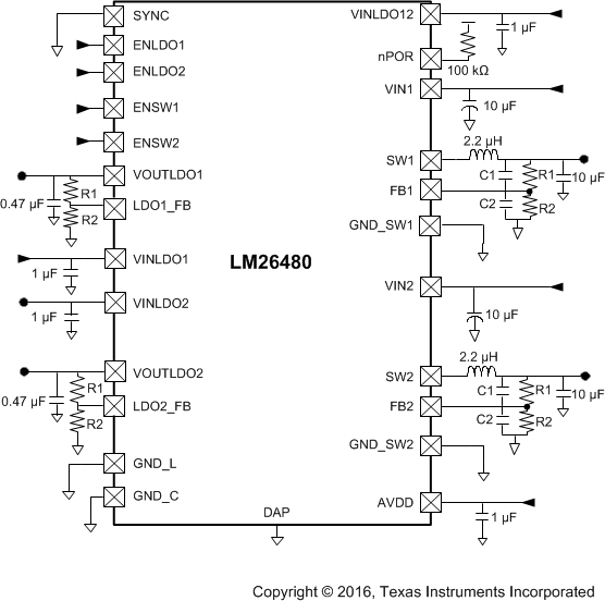
简化原理图

4 修订历史记录
Changes from B Revision (December 2016) to C Revision
- Added WEBENCH 的链接Go
- Deleted the maximum lead temperature (soldering) from the Absolute Maximum Ratings tableGo
- Changed the PBUCK1 and PBUCK2 equations in the Junction Temperature sectionGo
- Changed 静电放电注意事项 声明Go
Changes from A Revision (June 2016) to B Revision
- Changed 产品说明书的标题;将内容添加到说明部分Go
Changes from * Revision (January 2016) to A Revision