SLAU358Q September 2011 – October 2019
- Read This First
- 1Introduction
-
2Operation
- 2.1
Programming MSP Flash Devices Using the MSP Gang Programmer
- 2.1.1 Programming Using Interactive Mode
- 2.1.2 Programming From Image
- 2.1.3 Programming From Script
- 2.1.4 Programming in Standalone Mode
- 2.1.5 Memory Setup for GO, Erase, Program, Verify, and Read
- 2.1.6 Secure Device Setup and Memory Protection
- 2.1.7 Programming MCU With IP Encapsulated Segment
- 2.1.8 Serialization
- 2.1.9 Creating and Using Images
- 2.1.10 Programming From Image File
- 2.1.11 Programming From SD Card
- 2.1.12 File Extensions
- 2.1.13 Checksum Calculation
- 2.1.14 Commands Combined With the Executable File
- 2.2 Data Viewers
- 2.3 Status Messages
- 2.4 Self Test
- 2.5 Label
- 2.6 Preferences
- 2.7 Benchmarks
- 2.1
Programming MSP Flash Devices Using the MSP Gang Programmer
-
3Firmware
- 3.1 Commands
- 3.2 Firmware Interface Protocol
- 3.3 Synchronization Sequence
- 3.4 Command Messages
- 3.5
Detailed Description of Commands
- 3.5.1 General
- 3.5.2
Commands Supported by the BOOT Loader
- 3.5.2.1 "Hello" Command
- 3.5.2.2 Boot Commands Disable
- 3.5.2.3 Boot Commands Enable
- 3.5.2.4 Get Diagnostic Command
- 3.5.2.5 Select Baud Rate Command
- 3.5.2.6 Erase Firmware Command
- 3.5.2.7 Load Firmware Command
- 3.5.2.8 Exit from Firmware Update Command
- 3.5.2.9 Get Label Command
- 3.5.2.10 Get Progress Status
- 3.5.3 Commands Supported by Application Firmware
- 3.5.4
API Firmware Commands That Should Not be Used
- 3.5.4.1 Interactive Process Command
- 3.5.4.2 Erase Image Command
- 3.5.4.3 Read Info Memory From MSP-GANG Command
- 3.5.4.4 Write to MSP-GANG Info Memory Command
- 3.5.4.5 Verify Access Key Command
- 3.5.4.6 Write to Image Block Command
- 3.5.4.7 Verify Image Check Sum Command
- 3.5.4.8 Read Image Header Command
- 3.5.4.9 Disable API Interrupts Command
- 3.5.4.10 Display Message on LCD Display Command
- 3.5.4.11 Set IO State Command
-
4Dynamic Link Library for MSP-GANG Programmer
- 4.1 Gang430.dll Wrapper Description
- 4.2
MSP-GANG.dll Description
- 4.2.1 MSPGANG_GetDataBuffers_ptr
- 4.2.2 MSPGANG_SetGangBuffer, MSPGANG_GetGangBuffer
- 4.2.3 MSPGANG_GetDevice
- 4.2.4 MSPGANG_LoadFirmware
- 4.2.5 MSPGANG_InitCom
- 4.2.6 MSPGANG_ReleaseCom
- 4.2.7 MSPGANG_GetErrorString
- 4.2.8 MSPGANG_SelectBaudrate
- 4.2.9 MSPGANG_GetDiagnostic
- 4.2.10 MSPGANG_MainProcess
- 4.2.11 MSPGANG_InteractiveProcess
- 4.2.12 MSPGANG_Interactive_Open_Target_Device
- 4.2.13 MSPGANG_Interactive_Close_Target_Device
- 4.2.14 MSPGANG_Interactive_DefReadTargets
- 4.2.15 MSPGANG_Interactive_ReadTargets
- 4.2.16 MSPGANG_Interactive_ReadBytes
- 4.2.17 MSPGANG_Interactive_WriteWord_to_RAM
- 4.2.18 MSPGANG_Interactive_WriteByte_to_RAM
- 4.2.19 MSPGANG_Interactive_WriteBytes_to_RAM
- 4.2.20 MSPGANG_Interactive_WriteBytes_to_FLASH
- 4.2.21 MSPGANG_Interactive_Copy_Gang_Buffer_to_RAM
- 4.2.22 MSPGANG_Interactive_Copy_Gang_Buffer_to_FLASH
- 4.2.23 MSPGANG_Interactive_EraseSectors
- 4.2.24 MSPGANG_Interactive_BlankCheck
- 4.2.25 MSPGANG_Interactive_DCO_Test
- 4.2.26 MSPGANG_SelectImage
- 4.2.27 MSPGANG_EraseImage
- 4.2.28 MSPGANG_CreateGangImage
- 4.2.29 MSPGANG_LoadImageBlock
- 4.2.30 MSPGANG_VerifyPSAImageBlock
- 4.2.31 MSPGANG_ReadImageBlock
- 4.2.32 MSPGANG_Read_Code_File
- 4.2.33 MSPGANG_Save_Config, MSPGANG_Load_Config, MSPGANG_Default_Config
- 4.2.34 MSPGANG_SetConfig, MSPGANG_GetConfig
- 4.2.35 MSPGANG_GetNameConfig, MSPGANG_SetNameConfig
- 4.2.36 MSPGANG_SetTmpGANG_Config
- 4.2.37 MSPGANG_GetLabel
- 4.2.38 MSPGANG_GetInfoMemory, MSPGANG_SetInfoMemory
- 4.2.39 MSPGANG_Get_qty_MCU_Type, MSPGANG_Set_MCU_Type, MSPGANG_Get_MCU_TypeName, MSPGANG_Get_qty_MCU_Family, MSPGANG_Get_MCU_FamilyName, MSPGANG_Get_MCU_Name
- 4.2.40 MSPGANG_Set_MCU_Name
- 4.2.41 MSPGANG_HW_devices
- 4.2.42 MSPGANG_GetProgressStatus
- 4.2.43 MSPGANG_GetAPIStatus
- 4.2.44 MSPGANG_Set_IO_State
- 4.2.45 MSPGANG_Convert_Address
- 4.2.46 MSPGANG_Memory_Header_text
- 4.2.47 MSPGANG_Interactive_ClrLockedDevice
- 4.2.48 MSPGANG_Get_Code_Info
- 4.2.49 MSPGANG_MakeSound
- 4.2.50 MSPGANG_CallBack_ProgressBar
- 4.2.51 MSPGANG_GetPCHardwareFingerprint
- 4.2.52 MSPGANG_Flash_valid_addr
- 5Schematics
-
6Frequently Asked Questions
- 6.1 Question: Why does device init, connect, or programming fail?
- 6.2 Question: Can I use single wires for connection between MSP-GANG and target device?
- 6.3 Question: How to serialize parts?
- 6.4 Question: How to have parts run after programming?
- 6.5 Question: What are possible reasons for the part to fail Verify step?
- Revision History
2.1.2 Programming From Image
A programming configuration like the one created in Section 2.1.1 can be stored in the form of an image. The advantage of an image is that it contains both the configuration options necessary for programming as well as the code files that are flashed to target devices. Moreover, only images can be saved to internal MSP Gang Programmer memory and used in Standalone mode, in which the programmer can operate without being connected to a PC. Using the From Image mode allows the user to test images with full GUI support before committing them to production.
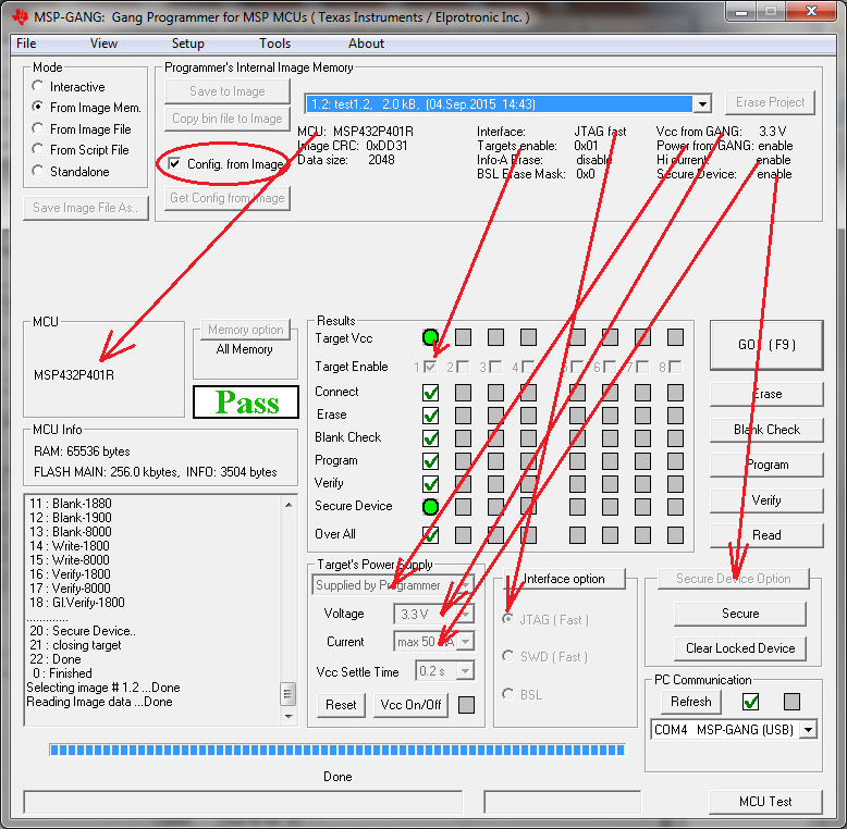
When an image has been created, it can be used to greatly simplify programming by using the procedure described in Section 2.1.9. Figure 2-6 shows the main dialog GUI where the From Image option is selected for programming (top left corner). Here the user can load an image from MSP Gang Programmer internal memory. An image can be created in Interactive Mode and saved to the programmer. One of 96 different images can be selected from internal memory, or one image from each external SD-Card can be used.
NOTE
MSP Gang Programmer internal memory and SD-Card are mutually exclusive.
To avoid confusion during programming, connecting an SD-Card to the MSP Gang Programmer disables its internal memory used for other images. Therefore, when an SD-Card is connected to the programmer only the image on the SD-Card is usable or accessible. If the SD-Card is empty, or contains a corrupted image, then it must be disconnected before MSP Gang Programmer internal memory can be used.

Figure 2-6 highlights several parts of the GUI. The drop-down menu in the Object in Image memory group (top right) is used to select which image is used for programming, because up to 96 different images might be available. In the same group, the Config. from Image option is enabled, meaning that all configurations options, such as which devices are enabled or power options are being taken from the image.
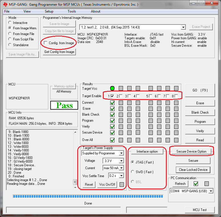
Sometimes it is useful to use the basic files from an image, such as the MCU type and code files, but also make a few minor modifications to test a different configuration. Figure 2-7 shows the additional configuration options available when the Config. from Image button is disabled. These are high-lighted in red and include which devices are enabled for programming, target VCC and current, interface, communication, and security. However, these changes cannot be committed to the image. If the user wishes to change the current image's configuration or code files then the image needs to be recreated using the original project file and procedure described in Section 2.1.9.
