ZHCSDS7A May 2015 – June 2015 LDC1101
PRODUCTION DATA.
- 1 特性
- 2 应用
- 3 说明
- 4 简化电路原理图
- 5 修订历史记录
- 6 Pin Configuration and Functions
- 7 Specifications
-
8 Detailed Description
- 8.1 Overview
- 8.2 Functional Block Diagram
- 8.3 Feature Description
- 8.4
Device Functional Modes
- 8.4.1 Measurement Modes
- 8.4.2 RP+L Measurement Mode
- 8.4.3 High Resolution L (LHR) Measurement Mode
- 8.4.4 Reference Count Setting
- 8.4.5 L-Only Measurement Operation
- 8.4.6 Minimum Sensor Frequency and Watchdog Setting
- 8.4.7 Low Power Modes
- 8.4.8 Status Reporting
- 8.4.9 Switch Functionality and INTB Reporting
- 8.5 Programming
- 8.6
Register Maps
- 8.6.1 Individual Register Listings
- 8.6.2 Register RP_SET (address = 0x01) [reset = 0x07]
- 8.6.3 Register TC1 (address = 0x02) [reset = 0x90]
- 8.6.4 Register TC2 (address = 0x03) [reset = 0xA0]
- 8.6.5 Register DIG_CONF (address = 0x04) [reset = 0x03]
- 8.6.6 Register ALT_CONFIG (address = 0x05) [reset = 0x00]
- 8.6.7 Register RP_THRESH_HI_LSB (address = 0x06) [reset = 0x00]
- 8.6.8 Register RP_THRESH_HI_MSB (address = 0x07) [reset = 0x00]
- 8.6.9 Register RP_THRESH_LO_LSB (address = 0x08) [reset = 0x00]
- 8.6.10 Register RP_THRESH_LO_MSB (address = 0x09) [reset = 0x00]
- 8.6.11 Register INTB_MODE (address = 0x0A) [reset = 0x00]
- 8.6.12 9.Register START_CONFIG (address = 0x0B) [reset = 0x01]
- 8.6.13 Register D_CONFIG (address = 0x0C) [reset = 0x00]
- 8.6.14 Register L_THRESH_HI_LSB (address = 0x16) [reset = 0x00]
- 8.6.15 Register L_THRESH_HI_MSB (address = 0x17) [reset = 0x00]
- 8.6.16 Register L_THRESH_LO_LSB (address = 0x18) [reset = 0x00]
- 8.6.17 Register L_THRESH_LO_MSB (address = 0x19) [reset = 0x00]
- 8.6.18 Register STATUS (address = 0x020 [reset = 0x00]
- 8.6.19 Register RP_DATA_LSB (address = 0x21) [reset = 0x00]
- 8.6.20 Register RP_DATA_MSB (address = 0x22) [reset = 0x00]
- 8.6.21 Register L_DATA_LSB (address = 0x23) [reset = 0x00]
- 8.6.22 Register L_DATA_MSB (address = 0x24) [reset = 0x00]
- 8.6.23 Register LHR_RCOUNT_LSB (address = 0x30) [reset = 0x00]
- 8.6.24 Register LHR_RCOUNT_MSB (address = 0x31) [reset = 0x00]
- 8.6.25 Register LHR_OFFSET_LSB (address = 0x32) [reset = 0x00]
- 8.6.26 Register LHR_OFFSET_MSB (address = 0x33) [reset = 0x00]
- 8.6.27 Register LHR_CONFIG (address = 0x34) [reset = 0x00]
- 8.6.28 Register LHR_DATA_LSB (address = 0x38) [reset = 0x00]
- 8.6.29 Register LHR_DATA_MID (address = 0x39) [reset = 0x00]
- 8.6.30 Register LHR_DATA_MSB (address = 0x3A) [reset = 0x00]
- 8.6.31 Register LHR_STATUS (address = 0x3B) [reset = 0x00]
- 8.6.32 Register RID (address = 0x3E) [reset = 0x02]
- 8.6.33 Register DEVICE_ID (address = 0x3F) [reset = 0xD4]
-
9 Application and Implementation
- 9.1
Application Information
- 9.1.1 Theory of Operation
- 9.1.2 RP+L Mode Calculations
- 9.1.3 LDC1101 RP Configuration
- 9.1.4 Setting Internal Time Constant 1
- 9.1.5 Setting Internal Time Constant 2
- 9.1.6 MIN_FREQ and Watchdog Configuration
- 9.1.7 RP+L Sample Rate Configuration with RESP_TIME
- 9.1.8 High Resolution Inductance Calculation (LHR mode)
- 9.1.9 LHR Sample Rate Configuration with RCOUNT
- 9.1.10 Setting RPMIN for LHR Measurements
- 9.1.11 Sensor Input Divider
- 9.1.12 Reference Clock Input
- 9.1.13 INTB Reporting on SDO
- 9.1.14 DRDY (Data Ready) Reporting on SDO
- 9.1.15 Comparator Functionality
- 9.2 Typical Application
- 9.1
Application Information
- 10Power Supply Recommendations
- 11Layout
- 12器件和文档支持
- 13机械、封装和可订购信息
1 特性
2 应用
- 高速轮齿计数
- 高速事件计数
- 电机转速感测
- 家用电器、汽车和消费类应用中的旋钮和拨盘
- 家用电器、汽车和消费类应用中的人机界面 (HMI)
- 按钮和键盘
- 电机控制
- 金属探测
3 说明
LDC1101 是一款 1.8V 至 3.3V、高分辨率电感数字转换器,可对位置、旋转或运动进行短距离、高速、无触点感测,即使存在污垢或灰尘也能够实现可靠、精确的测量,非常适合户外或严苛环境。
LDC1101 特有双感应测量内核,可在执行 > 150ksps 的 16 位 RP 和 L 测量的同时,进行分辨率高达 24 位的高分辨率 L 测量,采样速率可高达 180ksps 以上。 LDC1101 包含阈值比较功能,该功能可在器件运行时动态更新。
电感感测技术可实现对线性/角位置、位移、运动、压缩、振动、金属成分以及市面上包括汽车、消费类、计算机、工业、医疗和通信应用在内的很多其他应用的高精度测量。 电感感测技术能够以低于其他竞争对手解决方案的成本提供更为出色的性能和可靠性。
LDC1101 在小型 3mm × 3mm 10 引脚 VSON 封装内即可提供这些电感感测技术优势。 微控制器可使用 4 引脚 SPI™轻松配置 LDC1101。
器件信息(1)
| 器件型号 | 封装 | 封装尺寸(标称值) |
|---|---|---|
| LDC1101 | VSON (10) | 3.00mm × 3.00mm |
- 如需了解所有可用封装,请见数据表末尾的可订购产品附录。
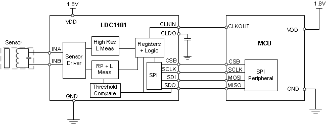
4 简化电路原理图
